


Thank you for purchasing the remote control unit for the Sterling
Alternator-to-Battery Charger. The remote control unit will let you
operate your charger with enhanced comfort and gives access to
additional functions.
Box Contents
remote control / display including mounting frame
2 shunts, rated 200amps continuously
2 battery cables, ca. 0.30m
remote control lead, ca. 8m
Required Tools and Parts
jigsaw (for flus mounting)
12mm drill (for top-mounting)
2mm drill
4 pcs. 45x3mm counter-sunk screws
Phillips screwdriver
two-core telephone or computer wire
Attention: Before starting to install the unit, disconnect
all power connections of the Alternator-to-Battery
Charger by disconnecting the batteries and the
alternator.
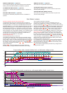
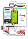
auxiliary contacts of the shunts to the corresponding connectors
on the alternator-to-battery charger . Mind the correct polarity
of the wires ! Reverse polarity on these wires may lead
to the amps being displayed incorrectly or even cause damage.
Therefore, make sure that each shunt connection is
connected with ist corresponding counterpart on the
alternator-to-battery charger.
Do not lay the remote control cable next to any 230volts a/c
cables or next to high current d/c cables. This may cause
Place of Installation
interference and erroneous data transmission. Remember, the
Install the remote control panel in a dry place and in such away
remote control cable is purely a data transmission working on
that you can easily read the display and access the control
very low voltages.
buttons.
We strongly recomend not to shorten this cable. If you cut and
reconnect the cable this may void the warranty of your unit.
The installation location should be accessible easily.
When all cables have been correctly laid and connected,
The remote panel can be flush-mounted or top-mounted with or
reconnect the batteries and the alternator.
without frame:
Functions
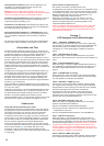
1) Top-Mounting with Frame
Drill a hole for the wires into the back board. Slide the small left
and right hand covers (A) off the front panel which will expose the
The alternator-to-battery charger can be switched on and off
screws. Unscrew, remove the frame (B) and drill the required
manually by pressing the on/off key. Even when the charger has
holes into the back board. Connect all necessary wires to the
been switched off, it will remain on standby mode. Also, the
correct terminals at the back of the unit. Mount the unit using the
batteries will still be charged, but without the boost on the
frame (B) and suitably long screws onto the back board.Reattach
domestic battery side. When the charger is switched off, the
the covers (A) onto the front panel.
remote control will display the voltage of the domestic battery.
After the unit has been switched on, the remote control will show
2) Top-Mounting without Frame
the software release of the charger and the remote control unit. In
case you are experiencing a problem with your alternator-to-
Slide the small left and right hand covers (A) off the front panel
battery charger, please take a note of these numbers before you
which will expose the screws. Unscrew and remove the frame
contact us.
(B). Use the inside of the frame (B) as a template for the required
cutout in the back board. Carefully cut out the back board and
When the engine is restarted, the alternator-to-battery charger will
connect all necessary wires to the correct terminals at the back of
also restart, even when the charger has been switched off
the unit. Mount the unit using the four short screws supplied and
manually before.
reattach the covers (A) onto the front panel.en.
2) Alarm Sound
3) Flush-Mounting
The alarm sound indicating any system faults can be muted using
the alarm key.
Remove the small left and right hand covers (A) off the front
panel and make a cutout of 134mm x 90mm into the back board.
Ideally, the back board should not be thicker than 3mm; otherwise
the front panel will stand back a little. Using the actual Power
The background light of the display panel can be switched on and
Management Panel as a template, drill the required holes with
off using the light key.
counterbores into the back board. Connect all necessary wires to
the correct terminals at the back of the unit. Push the unit from
behind into the cutout and fix it with the screws provided..
Display Functions
After the unit has been switched on, the unit will shortly display
the software release and then show the charging voltage and
Installation of Cables
current of the domestic battery bank (DOM) as well as the output
The shunts should be connected as shown in the wiring diagram
voltage and current of the alternator (ALT). To access further
(11, 12) using suitably rated battery cables (200amps minimum).
screens, use the following keys:
Then, using a regular telephone or computer wire, connect the
Important: The panel must be installed in a dry place!
(15)
(15a, 15b)
(a,b)
(a,b)
(13)Shunt Type Adjustment
The alternator-to-battery charger comes set up for the standard
Sterling 200A shunt (1mV = 1A). However it can be
reprogrammed for the use of a 500amp shunt (0.1mV = 1A).
Check your shunt type first before making any changes.
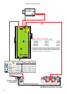
Installation of the Remote Control
Connect the supplied remote control cable with the remote control
unit. On the back of the remote panel is a small opening with a
socket behind. Mind the correct orientation of the plug when you
connect the cable. The small clip on top of the plug must be
directed upwards. Then, connect the remote control cable with
the corresponding connector on the alternator-to-battery charger.
Again, mind the correct orientation of the plug! (clip on top).
Basic Functions
1) Switching the charger on and off
3) Background Light
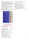
1) Key “volts” 2) System Disengaged (yellow)
This key will call the above mentioned standard screen. When the The alternator or the charger itself is overheated and the unit has
standard screen is displayed and this key is pressed again, the been deactivated temporarily. The charging process will
display shows the time since the unit has been switched on (ON) automatically be continued when the temperature has come
as well as the cumulative boost time (BOOST). down. It is not necessary to restart the system manually. If this
problem occurs frequently, improve the ventilation of the unit or
the alternator respectively.
2) Key “ê”
The display will show the voltage and the charging current of the
3) Low Voltage Warning (yellow)
starter battery and the calculated rest time of the absorption
The input voltage of the charger is too low and insufficient for its
charge.
proper functioning. Please check your connections and the output
voltage of your alternator.
3) Key “setup”
Pressing this key once will display selected battery type and the
4) System within Limits (green)
charging stage currently being active. When this key is pressed
All system parameters and functions are normal. The charger is
again, the boost will be displayed in per cent. Pressing this key a
working correctly.
third time will show the software release of the remote control (R)
and the charger (C) as well as the system voltage.
Special Functions
4) Key”temp”
Auto-Pause Function
Pressing this key once will display the temperature of the
The alternator-to-battery charger is programmed in such a way
alternator (ALT) and the temperature of the battery (BAT). (In
that the boost function is suspended for the first five minutes after
case of the temperature sensors not being used, the display will
switching on and every 20 minutes for a period of three minutes
show 20 deg C.) If this key is pressed again, the left hand (LHS)
thereafter. This is called the auto-pause function which gives the
and right hand (RHS) interior case temperatures will be
starter battery an extra charge. It can be manually deactivated by
displayed.
pressing the “volts” and the “ê” keys at the same time. To
confirm you will hear a beep and see a text message on the
screen.
LED Display on Remote Control
Every time the unit is switched off and back on again, the auto-
1) System Trip (red)
pause function will be reactivated automatically.
The charger has tripped and switched off because of a non-
recoverable fault. The system has to be restarted manually.
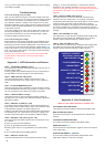
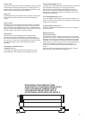
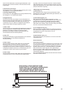
REMOTE CONTROL
INSTRUCTIONS
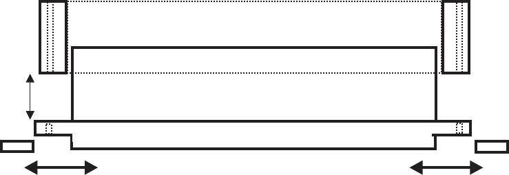
A
B
BOX INSTALLATION INSTRUCTIONS
SLIDE PARTS A TO EXPOSE SCREW HOLES
FOR FLUSH MOUNT, REMOVE PART B
FOR SURFACE MOUNT KEEP PART B
AFTER INSTALLATION REPLACE PARTS A
6 7