


English
Please read these instructions before use!
INSTRUCTIONS
- Position the charger in a cool, dry and well-ventilated
space, ensuring a reasonable airflow around the charger.
Do not install in a cupboard or in a sealed compartment.
- Install as close to the batteries as possible, preferably within
2 metresof the batteries.
- This unit is fitted with an automatic 110V/230V crossover
switch. As such the following input voltage may be used :
80V-130 V or 170V-280V at any frequency between 40Hz
and 400Hz.
- See the chart on the next page to select the correct cable
size. in the event you cannot get the correct cable thickness (
thick cable is sometimes hard to acquire ) then simply run 2
or 3 etc lengths of thinner cable to make up the correct
copper area.(See Table 1.)
As per U.K.. law only aqualified electricianshould install this
product.
- Before switching the charger on, it is important to set up the
battery type. Please choose a battery type according to
Fig.1. Sterling have supplied 7 different settings, and have
tried to encompass all battery types and there charge rates,
why the Americian settings differ from the European settings
for the same batteries I have no idea, however we supply
both, please have that argument with your battery supplier
and not Sterling. If in doubt always chose the setting with the
lower voltage until such time you can confirm the correct
setting.As a rule of thumb, thehigher the charge voltage the
faster a battery will charge but the more gas may be
produced. gassingof sealed batteries isnot recommended
- When different types of batteries are to be charged, the
battery type with the lowest Charge and absorption voltage
must be selected. Never charge a battery on a higher setting
than itshould!
-H
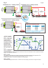
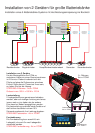
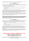
- Connect the cables as indicated in Fig 3.
Where only one
battery is being charged, connect the surplus positive
output terminals to the other used output terminal. This
ensures correct regulation; failure to do this could reduce
the chargingperformance.
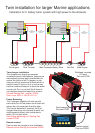
- The charger may be mounted in any position. Always
connect the cables to the charger first, then run them to
the batteries. Never connect any cables to the batteries
before runningthem to the charger!
- The charger case is earthed as per
international regulations. On most boats, the A/C earth is
connected to the bonding system and then to the negative
of the battery.This means that the case could be negative.
If a positive battery cables touches the case, this can set
up a dead short to the battery negative via the earth cable
and meltthe earth cable; thiscould start afire.
aving set the battery type the charger should be installed
and will only need to be altered if there is a change in battery
type orsize.
Warning:
Always ensure
that all the terminals are being used!
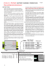
Apply AC power, after approximately 6 seconds the LEDs will
illuminate. Battery type LED will be lit to indicate battery
type selected. The Fast Charge and Absorption Charge
LEDs will both initially illuminate and after 5 minutes the
Absorption LED will extinguish .This is a hold function to
keep the charger from going toAbsorption in the case of a
totally dead high resistance battery. None of the Fault
LEDs should illuminate, it is possible that the Under
Voltage yellow LED will be on if the batteries are in a
deeply discharged condition. This LED will extinguish as
the batteries charge in up to 3 to 4 hours depending upon
the capacity of the battery banks. The charger modes are
as follows Fast Charge, Absorption, Float and
Reconditioning
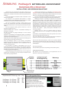
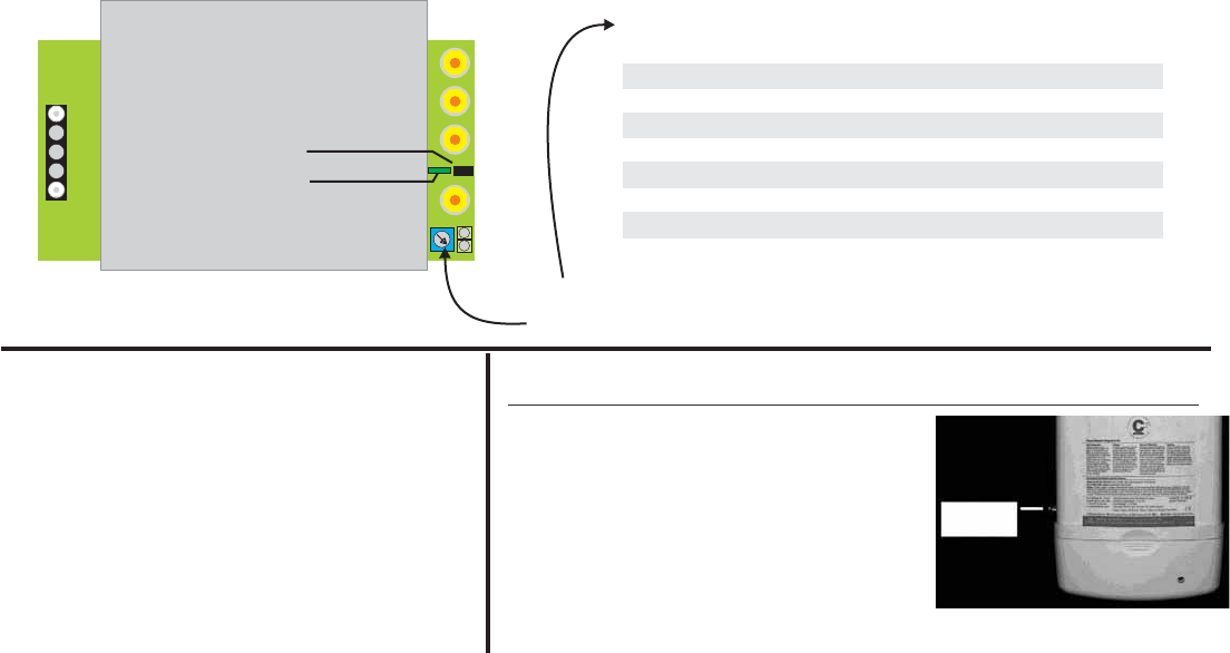
Please fit the temperature
sensor to the negative terminal of one of the batteries on
the mostactive battery bank.
Temperature Sensor Installation.
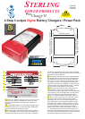
STERLING
ProTech BATTERY CHARGER / POWER PACK
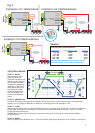
Fig. 1
2
+
BATTERY TYPE
SELECTOR
+
+
+
+
+
+
LIVE
NEUTRAL
EARTH
POSITIVE
POSITIVE
POSITIVE
NEGATIVE
REMOTE CONTROL
FUSE
Switch
Postion
High Charge &
Float voltages
Battery type
Recommended A/C Fuse Breaker amps
110 v 230 v
Pro Charge 12 v 50 amp 16a 8a
Pro Charge 12 v 60 amp 18a 9a
Pro Charge 24 v 30 amp 20a 10a
1 14.0 H 13.7 F x 2 for 24 v Gel 1
2 14.3 H 13.3 F x 2 for 24 v AGM
3 14.4 H 13.6 F x 2 for 24 v Sealed Lead acid
4 14.4 H 13.8 F x 2 for 24 v Gel 2
5 14.6 H 13.7 F x 2 for 24 v AGM 2
6 14.8 H 13.3 F x 2 for 24 v Open lead acid
7 15.1 H 13.6 F x 2 for 24 v Calcium
8 15.5 De-sulphation mode x 2 for 24 v
DC Grounding
Connection
DC Grounding Connection
The case DC grounding connection should be
connected to the boats DC engine negative buss
terminal using a cable one size smaller than the
negative battery cable.
After all cables are in place recheck
connections making sure all connections are
tight, confirm the charger is in a dry location.