


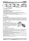
STUDER Innotec
XP-COMPACT
User manual XP-COMPACT V5.1 E 17
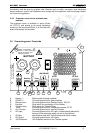
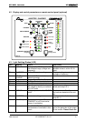
5.3 Battery Condition
Built-in microprocessor calculates the actual state of charge of the battery and displays it on LED
15 – 18. The LED 14 is lit when the system is carrying out a charge cycle with equalization.
The voltage levels and charge characteristics can be changed through Programming. The instruc-
tion for programming of battery levels is in the section „Programming”
5.4 Fault indicator
5.4.1 Overtemp. (10)
For the time being the XP-COMPACT is out of service because of overheating due to high ambient
temperature or excessive overload
5.4.2 Overload (11)
The LED indicator lights when the inverter is suffering a load higher than the permitted overload
during more than 5 seconds.
5.4.3 Battery low/high
The LED indicator lights when the battery voltage is too low and blinks when it is too high.
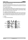
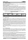
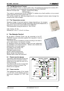
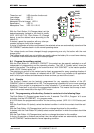
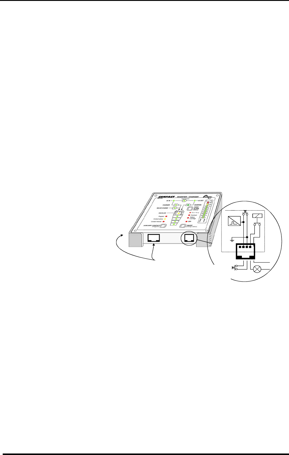
5.5 Remote alarm contact and on/off control
In the Remote Control there is an additional Alarm Contact and a Control Input built in. These two
functions are available through Tip-
jack RJ11/4 for use. This Auxiliary
Contact is Front / Work Contact
(max. 0.5A!), which is independent of
the Auxiliary Contact of the XP-
COMPACT. This contact is active in
case of an alarm of the XP-
COMPACT.
The Control Input is connected in
parallel to the ON/OFF- push button.
The XP-COMPACT can be switched
on or off through this input with an
impulse button or an impulse contact.
Order Number for Remote Control: RCC-01
Dimensions: H x B x T / 111.5 x 136.5 x 25mm
Caution: No external voltage should be connected to this Input Control.
5.6 Manual control of the auxiliary contact
The auxiliary Contact can be operated at any time with the Push Button 21 (AUX. CONTACT). The
LED 6 „Contact manual“ lights up as information that the Contact is manually operated, and LED 5
„Contact active“ lights up when the Contact is active. By pushing the Push Button 21 a second
time, the Contact is deactivated. By pushing it the third time, automatic functions are restored.
When the auxiliary contact is manually controlled (LED 6 lit) the programmed control of the contact
is disabled. In program mode, the auxiliary contact may be automatically actuated by every dis-
played status of the XP-COMPACT. Refer to chapter 6.4 for programming the auxiliary contact.
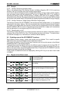
6 Programming
Programming the charging parameter and the auxiliary contact is only possible thru the optional
remote control. This programming allows to changing the factory setting parameters for battery
management and auxiliary contact.
1 2 3 4
ON/
OFF
! -
batt
!
Remote contorl
60V/0,5A
max
.
Remote
control
COMPACT
only
Dry contact