STUDER Innotec
XP-COMPACT
User manual XP-COMPACT V5.1 E 7
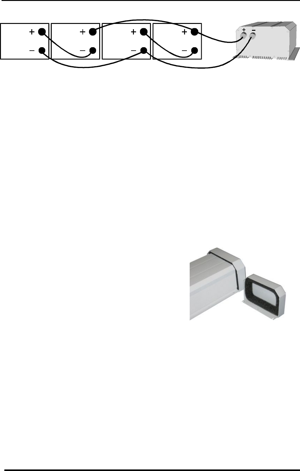
2.3.3 Connection in parallel and in serie
3 Mounting and installing
3.1 Installation place
The location of the XP-COMPACT must be chosen by the following criteria:
- Protection against unauthorized handling
- Dry dust free room, no condensation
- Never install directly over the battery and never in a cabinet together with the batteries
- Keep ventilation holes free. The ventilation of XP-COMPACT is designed in such a way that it can
only work efficiently when the appliance is fully lying on its back
In mobile installations it is important to keep down the vibrations as low as possible.
3.2 Fixing
3.2.1 XP-COMPACT
Basically the XP-COMPACT can be installed in any desired location. Preferred is that the appli-
ance be wall mounted with battery cables downwards. The XP-COMPACT is fixed on the wall with
four screws through the four holes (diam. 5.5mm) which are accessible from the outside. In motor
vehicles XP-COMPACT must be fixed on vibrations reducing elements. The XP-COMPACT must
not be fixed on a combustible base, as the back of the casing can get hot and reach up to 80 de-
gree Celsius.
3.3 Protection cover IP23
This cover IP23 (Order ref. C-IP23), can be easily ins-
talled after the fixation of the XP-COMPACT. To install it,
release a little the too screws down and more the two up.
Then insert the IP 23 cover between the XP-COMPACT
and the wall. The cover must touch the screws. Lock on
the four screws, it’s ready.
3.4 Connections
3.4.1 General instructions on connecting
The cable connection on the terminals AC INPUT / AC OUTPUT / 16A 230VAC are carried out
with a screwdriver Nr.1 and the connection on the SOLAR terminal with a screwdriver Nr.2.
The conductor cross section on the terminals AC INPUT / AC OUTPUT / 16A 230VAC of the con-
necting cable must be minimum 2.5mm
2
.
All connecting cables and also the mounted battery cables must be fixed with strain relief clamps.
The XP-COMPACT is delivered with battery cables already connected.
The battery cables must never be extended. If the extension can not be avoided, then the conduc-
tor cross section must be elevated accordingly.
To protect the battery cable, a fuse corresponding to the conductor cross section must be fixed
directly on to the battery.
All cables must be tightly screwed in place. For safety, a yearly control is recommended. In mobile
installations control must be carried out more often.
12V 12V 12V 12V
24V


