


Best Practices for the Sun StorEdge 3510 FC Array 5
With at least one LD assigned to each controller, both controllers are active. This
configuration is known as an active-active controller configuration and allows
maximum use of a dual controller array's resources.
Each LD can be partitioned in up to 128 separate partitions or used as a single
partition. The partitions are presented to the host as LUNs.
Once the LDs have been created, assigned to a controller, and partitioned, the
partitions must be mapped to host channels as LUNs in order for them to be seen by
a host. It is usually desirable to map each partition to two host channels for
redundant pathing.
A partition can only be mapped to a host channel where its controller has an
assigned ID. For example, if LD 0 is assigned to the primary controller, all partitions
on LD 0 will need to be mapped to a host channel ID on the primary controller
(PID). Any LDs assigned to the secondary controller will need to have all partitions
mapped to a host channel ID on the secondary controller (SID).
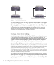
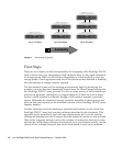
When attaching fibre cables for LUNs configured with redundant paths, make sure
one cable is connected to an upper port channel and the other cable is connected to
a different channel on the lower controller. Then, if multipathing software is
configured on the host, a controller can be hot-swapped in the event of failure
without losing access to the LUN.
For example, suppose partition 0 of LD0 is mapped to Channel 0 PID 42 and
Channel 5 PID 47. To ensure that there is no single point of failure (SPOF), connect a
cable from the host HBA or a switch port to the upper board port FC0, and connect
a second cable from the lower board port FC5 to a different host HBA or switch.
Cache Optimization
The Sun StorEdge 3510 FC array can optimize the RAID devices for either sequential
I/O or random I/O. Sequential I/O is the default setting.
The sequential optimization mode reads and writes data in large 128K blocks, in
order to transfer information more efficiently for the kinds of applications most often
employed. The logical drive, cache memory, and other controller internal parameters
are adjusted for high throughput use such as video and imaging applications. The
maximum allowable size of a logical drive optimized for sequential I/O is 2
terabytes (TB).
The random I/O optimization mode reads and writes data in small 32K blocks.
When using random I/O optimization mode, the logical drive, cache memory, and
other controller parameters are adjusted for the use of database/transaction-
processing applications. The maximum allowable size of a logical drive optimized
for random I/O is 512 GB. This limit constrains the number of disks that can be
included in a logical drive.