8
TASCAM CG-2000
2 – Names and functions of parts
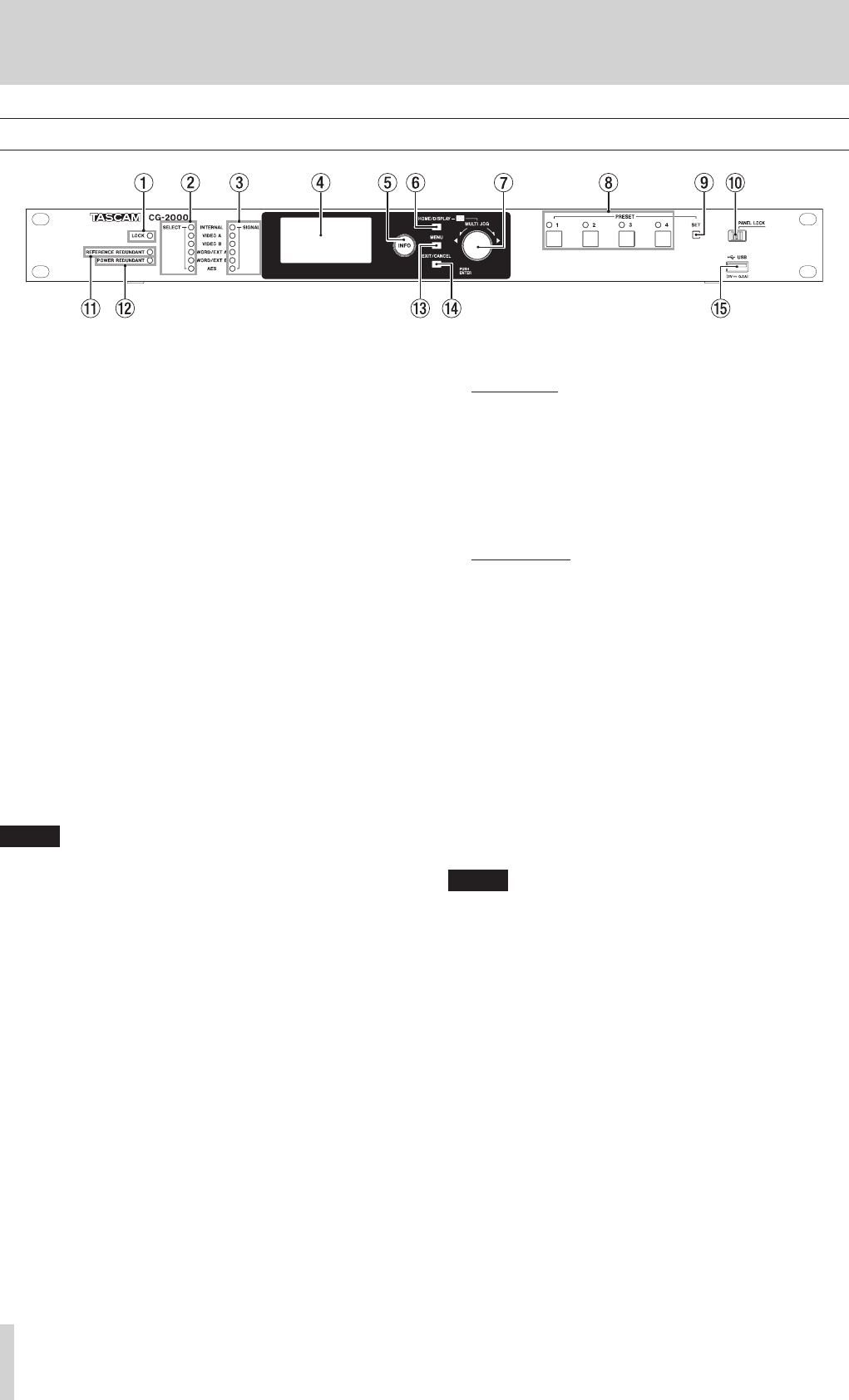
Front panel
1
LOCK indicator
This shows if the output clock and reference clock are
locked.
Lit: The output clock phase is synchronized with the
reference clock phase.
Blinking: The output clock phase is not synchronized
with the reference clock phase.
Examples:
o When the reference clock is being chased when it is
switched by the reference redundancy function
o When the backup reference clock is operating
2
SELECT reference clock indicators
This shows the selected reference clock and its operation
status.
Lit: Now selected and used for reference (including
secondary)
Blinking: Selected for reference, but not being used
Unlit: Reference clock that is neither selected nor being
used
3
SIGNAL indicators
This shows the input status of each reference clock signal.
Lit: Clock is being input and is locked
Blinking: Clock is being input but is not locked
Unlit: Clock is not being input
NOTE
The INTERNAL indicator will blink to show the temperature
of the constant temperature control tank is unstable for
about three minutes after the OCXO (oven-controlled
crystal oscillator) is started as well as if the temperature of
the constant temperature control tank is irregular.
4
Display
This shows various information.
5 INFO indicator/button
Lit blue: Indicates ordinary operation. Press the INFO
button to show the status of the unit on the display.
Lit red: Indicates trouble. Press the INFO button to show
information about the error on the display. Press again
to show the status of the unit.
6 HOME/DISPLAY button
Press when a menu screen is open to return to the Home
Screen.
While pressing and holding this button, turn the MULTI JOG
dial to adjust the brightness of the display and the various
indicators.
7 MULTI JOG dial
This dial also functions as a button.
Dial functions
In menu mode, use to select menu items and setting
values.
While pressing and holding the HOME/DISPLAY button,
turn the MULTI JOG dial to adjust the brightness of the
display and the various indicators.
When the
INFORMATION
screen or the
ERROR
INFORMATION
screen is open, turn the MULTI JOG
dial to scroll through various information.
Button function
Use as the ENTER button to confirm selections and
settings.
8
PRESET indicators/buttons (1–4)
Use these buttons to save and recall preset settings. (See
“Recalling presets” on page 21.)
Ordinarily, the indicator for the button of the most recently
recalled preset is lit
9 SET button
Press to save the current settings to one of the PRESET
buttons. (See “Saving the current settings as a preset” on
page 21.)
0 PANEL LOCK switch
Slide this switch to the right to disable all operation from the
front panel. To enable operation from the front panel, slide
this switch to the left.
NOTE
The INFO and HOME buttons, as well as the
INFOR-
MATION
and
ERROR
Information screens can still be used.
q REFERENCE REDUNDANT indicator
This shows the operation of the reference redundancy
function.
Lit: The reference redundancy function is on and both
the primary and secondary reference clocks are locked.
Blinking: The reference redundancy function is on and
either the primary or secondary reference clock is not
locked, or the reference clock is set to INTERNAL.
Unlit: The reference redundancy function is off.
w POWER REDUNDANT indicator
This shows the operation of the power redundancy function.
Lit: The power redundancy function is on and both
circuits are operating.
Blinking: The power redundancy function is on, but only
one circuit is operating.
Unlit: The power redundancy function is off.
e MENU button
When the Home Screen is open, press this button to open
the menu screen.


