


Teledyne API M452 Ozone Sensor Instruction Manual, 02852, Rev. E
4-4
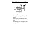
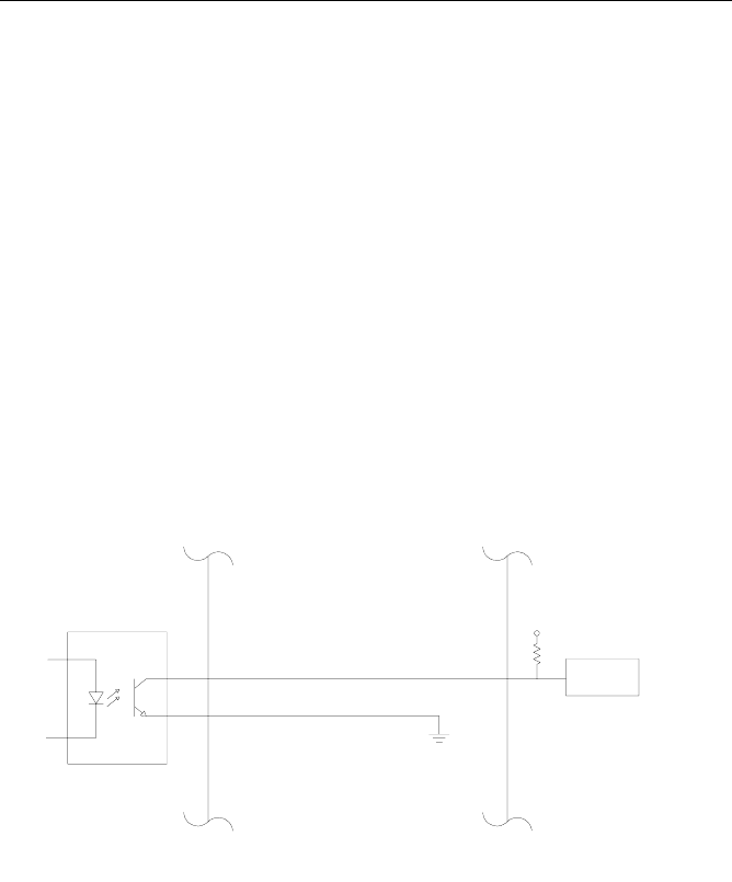
4.3.4 Status Outputs
The M452 has four digital status outputs for indicating error status and
when operational parameters have moved out of normal limits. These
outputs are in the form of opto-isolated open-collector transistors. They
can be used to drive status LED’s on a display panel or interface to a
digital device such as a Programmable Logic Controller (PLC).
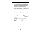
Figure 4-2 below shows the most common way of connecting the digital
outputs to an external device such as PLC. Note: Most devices, such as
PLC’s, have internal provision for limiting the current that the input will
draw from an external device. When connecting to a unit that does not
have this feature, external dropping resistors must be used to limit the
current through the transistor output to 50mA or less.
See Section 1 for details on using the Status Outputs for diagnosing sensor
and system-level malfunctions.
Opto-Isolator
Digital Output #1-4 (Collector)
Digital Output Common (Emmiter)
Ground Provided
by PLC
Programmable Logic
Controller or other device
M452
Digital
Input
+5V
Figure 4-2: Digital Output Connections