


www.ti.com
Equipment
1.4 Recommended Operating Conditions
Table 2. Recommended Operating Conditions
Symbol Description Min Typ Max Unit
Vin, J1 Supply Voltage 9.5 10.0 10.5 V
Vout, J4 Battery Voltage (3-cell lead-acid battery) 4 7.5 V
Iin Supply Current 0 0.5 A
Iout Charge Current 0 0.5 A
2 Equipment
2.1 Power Supplies
Power Supply #1 (PS#1): Adjustable from 0 to ≥ 10 VDC at ≥ 1A; used for input J1.
Power Supply #2 (PS#2): Adjustable from 0 to ≥ 10 VDC at ≥ 1.5A; used for Battery Load Board.
2.2 Loads
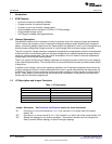
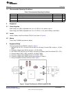
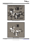
Load #1: Battery Load Circuit Board, PR1010-2, as shown in Figure 2.
2.3 Meters
Three Fluke 75 DMMs (equivalent or better).
3 Equipment Setup
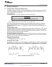
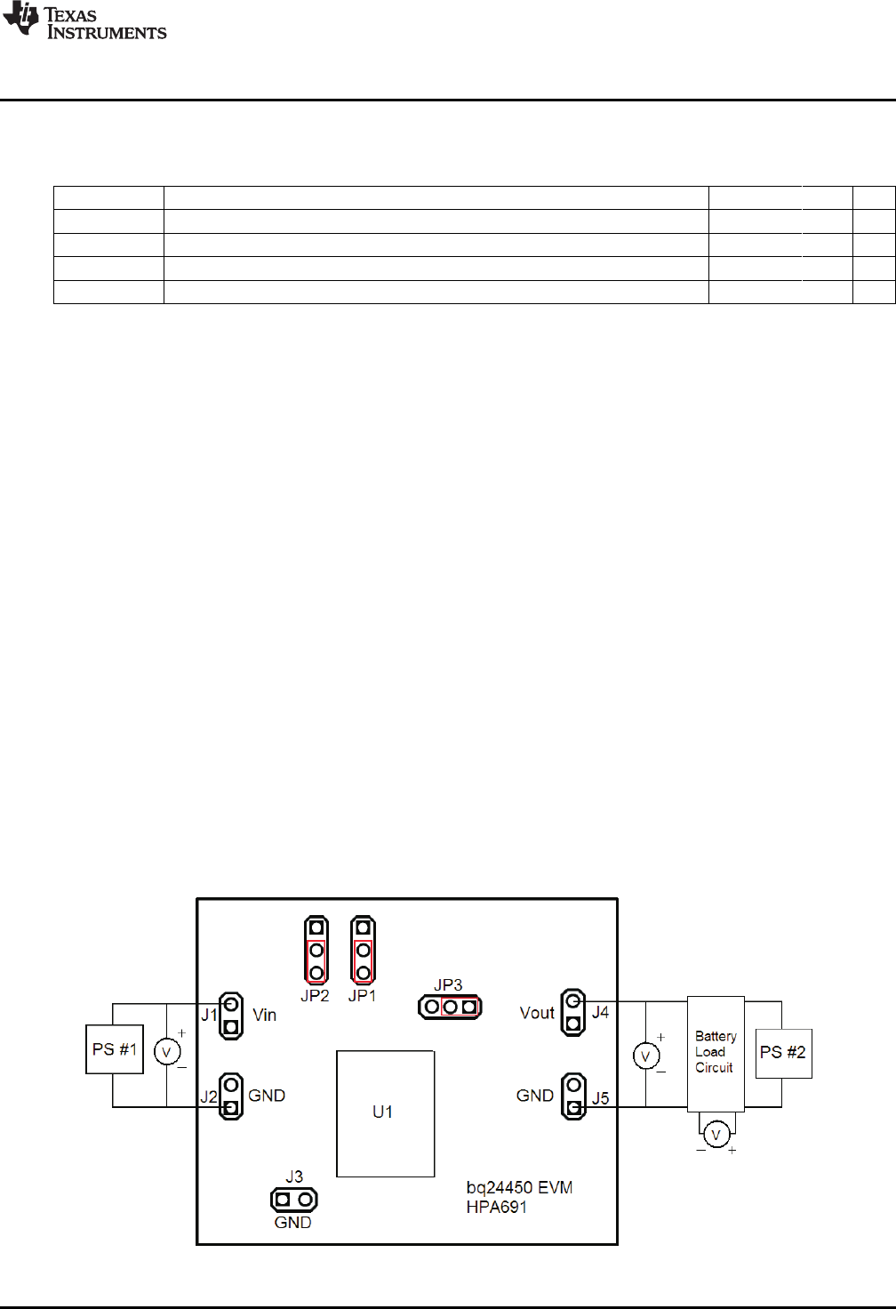
The original test setup of HPA691 is shown in Figure 1.
1. Set the PS #1 for 10V, 1A current limit and then turn off supply. Connect PS#1 across J1, J2 (VIN,
GND).
2. Connect a voltage meter (VM #1) across J1, J2 (VIN, GND)
3. Set PS#2 to 5.2V and then turn off supply. Connect to the Battery Load Circuit Board (P/S+, P/S–)
4. Connect Load #1 (BAT+, BAT–) across J4, J5 (VOUT, GND).
5. Connect a voltage meter (VM#2) across J4, J5 (VOUT, GND).
6. Connect a voltage meter (VM#3) across sense resistor on Load #1.
7. Verify the jumpers are placed correctly as per, Figure 1.
Figure 1. Original Test Setup for HPA691 (bq24450 EVM)
3
SLUU464–November 2010 bq24450EVM
Submit Documentation Feedback
© 2010, Texas Instruments Incorporated