


19
Equivalent pressure drops
To correctly determine the size of the
liquid and discharge lines for
connection on site, it is first
necessary to establish the equivalent
pressure drops for each line,
comprising the additional flow
resistances, from bends, valves, etc.
As a first approximation, we can
estimate the equivalent pressure
drops at 1.5 times the piping length.
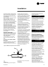
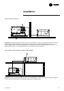
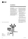
Size of the liquid line
The standpipe must not be more
than 5 m above the air-cooled
condenser base. It is not necessary
to slope the liquid line. It is
recommended to have a line
diameter as small as possible, while
maintaining an acceptable pressure
drop so as to minimize the
refrigerant charge (length and
maximum pressure drops defined
above).
Determine the size using the
following criteria:
1. Operating conditions with full load
2. Maximum pressure drops of
100-kPa
3. Liquid speed not exceeding 3 m/s
(to prevent liquid shocks)
In normal operating conditions
(suction temperature 4.5°C,
condenser air inlet temperature 35°C
or condensation temperature of
52°C), the liquid leaving the
condenser is sub-cooled by
approximately 10°C. Take this value
as a basis to determine the
maximum permitted pressure drops,
and use it to calculate the liquid line
pressure drops.
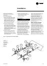
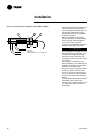
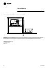
Discharge line
Install them so as to obtain a gas
speed in the horizontal and vertical
lines making it possible to carry
along the compressor oil. Determine
the dimensions of the suction line
using the following criteria:
1. 2.5 m/s (minimum) in the
horizontal parts
2. 5.0 m/s (minimum) in the vertical
parts
3. Maximum speed 20 m/s
The minimum slope of the suction
line to the condenser must be 5%.
Isolate refrigerant fluid lines from the
building to prevent the vibrations
normally generated by the ducts
from being transmitted to the
building's structure. Also avoid
bypassing the unit's isolation system
by fixing the refrigerant fluid lines or
the electrical ducts very rigidly. Any
vibrations may be propagated into
the building via rigid piping or lines.
Pressure tests and leak
detection
ƽƽ WWAARRNNIINNGG
During these operations, take the
following precautions:
1. Do not use oxygen or acetylene
instead of the refrigerant fluid and
nitrogen to detect leaks. This may
cause a violent explosion.
2. Always use the expansion valve,
safety valves and manometers to
control the test pressure in the
system. Excessive pressure may
cause piping to rupture, damage
the unit or cause explosion
resulting in personal injury.
Carry out the liquid line and hot gas
line pressure tests using the
standards in force. The test pressure
applied to the liquid line and the
discharge line must comply with
local regulations. Insert enough
refrigerant fluid into the circuit to
obtain a pressure of 1 bar.
By injecting dry nitrogen using a
pump, increase this pressure to
7 bars. Look for leaks in the entire
system using a detector.
If leaks are detected, evacuate the
fluid from the system and repair the
defective component. Repeat the test
process to check the repair is
watertight.
Installation
RLC-SVX03A-E4