


29
The evaporator is large enough to
hold all the charge, for any unit,
below the centerline of the shell.
Therefore, no special precautions are
required to restart the unit after
isolating the charge in the
evaporator.
Filter Replacement
Procedure
A dirty filter is indicated by a
temperature gradient across the
filter, corresponding to a pressure
drop. If the temperature downstream
of the filter is 8°F [4.4°C] lower than
the upstream temperature, the filter
should be replaced. A temperature
drop can also indicate that the unit is
undercharged. Ensure proper
subcooling before taking
temperature readings.
1. With the unit off, verify that the
EXV is closed. Close the liquid-line
isolation valve. On units with
remote evaporators or oil cooling
circuits, close the ball valve on the
oil cooler liquid line.
2. Attach the vacuum hose to the
service port on the liquid-line filter
flange.
3. Evacuate the refrigerant from the
liquid-line and store.
4. Remove the vacuum hose.
5. Depress the Schrader valve to
equalize pressure in the liquid line
with atmospheric pressure.
6. Remove the bolts that retain the
filter flange.
7. Remove the old filter element.
8. Inspect the replacement filter
element and lubricate the o-ring
with Trane OIL00048.
ƽƽ CCAAUUTTIIOONN
Do not use mineral oil. It will
contaminate the system.
9. Install the new filter element in the
filter housing.
10. Inspect the flange gasket and
replace it with a new one if
damaged.
11. Install the flange and torque the
bolts to 14-16 lb-ft [19-22 n-m].
12. Attach the vacuum hose and
evacuate the liquid line.
13. Remove the vacuum hose from
the liquid line and attach the
charging hose.
14. Replace the stored charge in the
liquid line.
15. Remove the charging hose.
16. Open the liquid-line isolation
valve. On units with remote
evaporators or oil cooler circuits,
open the oil cooler liquid-line ball
valve.
Lubrication System
The lubrication system has been
designed to keep most of the oil
lines filled with oil as long as there is
a proper oil level in the oil sump. The
total oil charge can be removed by
draining the oil system, the oil return
line from the evaporator, the
evaporator, and the compressor. Very
small quantities of oil may be found
in other components.
Oil Charging Procedure
Proper charging of the oil system is
critical to the reliability of the
compressor and chiller. Too little oil
can cause the compressor to run hot
and inefficiently. When taken to an
extreme, low oil level may result in
infant failure of the compressor. Too
much oil will result in high oil-
circulation rates, which will foul the
condenser and evaporator
performance. This will result in
inefficient operation of the chiller.
Taken to an extreme, high oil levels
may result in erratic expansion-valve
control or shut down of the chiller
due to low evaporator-refrigerant
temperature. Too much oil may
contribute to long-term bearing
wear. Additionally, excessive
compressor wear is probable when
the compressor is started with the oil
lines dry. Oil system consists of the
following components:
• Compressor
• Oil separator
• Discharge line with service valve
• Oil line from separator to
compressor
• Oil line drain (lowest point in
system)
• Oil cooler
• Oil temperature sensor
• Oil line shutoff valve with flare
service connection
• Oil filter (internal to compressor)
with flare-fitting service connection
and Schrader valve
• Oil flow-control valve (internal to
the compressor after the filter)
• Oil return line from evaporator with
shutoff valve, strainer, and solenoid
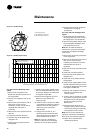
control valve. The standard oil
charge for each circuit size is shown
in Table 1.
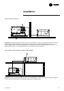
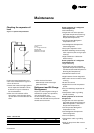
Measuring the oil level
1. To measure the oil level, use the
oil drain valve on the oil line and a
service valve on the discharge line.
This measurement can only be
made when the circuit is not
running. Note: the bottom plate of
the oil separator is approximately
1" [25 mm] thick.
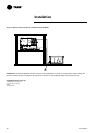
2. The initial oil charge should be
approximately at the level as
shown in Table 6. This is the
approximate oil level if all the oil is
in the oil lines, filter, and oil sump,
and the unit is in vacuum so that
there is no refrigerant dissolved in
the oil.
3. After the unit has run for a while,
the oil level in the sump can vary
greatly.
The field-charging procedure
depends on the circumstances that
resulted in the need for oil charge.
1. Some service procedures may
result in loss of small quantities of
oil that must be replaced (oil
analysis, compressor filter
replacement, re-tubing the
evaporator, and so forth).
2. Additionally, some maintenance
procedures may result in virtually
all of the oil being removed
(compressor motor burn or total
removal of the charge to trouble-
shoot a unit).
3. Finally, leaks may result in a loss
of oil that must be replaced.
Maintenance
RLC-SVX03A-E4