


3
To enable the factory to respond efficiently to
manufacturing requests, the equipment purchase order
must contain the following information in addition to the
model and options.
1. The application and as much contaminate load data
as possible. This will enable the wash control to be
preset and adjusted to the optimum setting.
2. The high-voltage lead length required if longer than
the standard length of 50 feet.
3. The side of the blower section the blower motor
starter is to be installed. Left or right as determined
when standing in the direction of air flow with the air
striking your back.
4. The external static pressure that the blower/motor
will handle due to ducting, hooding or other
equipment.
Contact the local Trion Sales Office or the factory if
questions arise, or if any additional information is
required.
SECTION II INSTALLATION
FOR THE INSTALLING CONTRACTOR
1. Unpack and Inspect
At the time the unit is received, all shipping containers
and their contents should be examined for damage. Any
damage occurring in shipment must be immediately
reported to the carrier, an inspection report completed
and a claim filed at the receiving point.
The unit modular sections are shipped completely
assembled and joined and, where size permits, the
electronic air cleaner ionizing-collecting cells are
shipped inside the cabinet. On large units, the upper tier
of cells may be shipped in separate containers. The
wash control, detergent feeder and other separate
accessories are shipped in the containers as noted on
the packing list.
2. Position Air Cleaner Cabinet
If advantageous, to remove weight for ease in handling,
the filtration elements can be removed from their
respective cabinets. Position the unit in the designated
location giving consideration to the following points:
(a) Excluding the blower section, there are access
doors on one side of the section modules. Provide
sufficient clearance in front of the doors on at least
one side for service and element removal. Normally
the side on which the factory installed blower motor
starter is mounted is the pre-planned side for single
side access.
(b) Level the unit to assure proper drainage from the
drain pans.
After the cabinet has been properly located, it may be
secured into place by bolting or welding. Reinstall any
section elements removed during installation making
directional arrows concur with the designed airflow
through the cabinet.
3. Connect Adjoining Duct Work
When the adjoining ducting is installed on the air
entering side, the bottom of the horizontal duct run
should be relatively flat and sloped toward the section
housing drain pan for an 18-inch length. This will enable
any wash water splashback occurring during the
washing operation to run back into the drain pan.
Secure the adjoining ducting to the section housing
utilizing the .375-inch clearance holes provided. The
seams should be made air and watertight by caulking or
gasketing.
Upstream ducting conveying warm air and subjected to
cold temperatures must be insulted to prevent
excessive condensation.
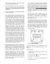
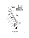
4. Mount Detergent System
Refer to Figures 1 and 4. The detergent system should
be located as close to the unit as practical in a level
position. Service space must be provided for periodical
manual filling of the detergent tank, and to gain access
to the pump and motor assembly. When positioned, the
assembly may be secured in place at the predrilled
factory mounting pads, either by bolting or welding.
5. Connect Drain
Connect a drain line to the 2” NPT couplings provided in
the drain basins of the impinger and electronic air
cleaner sections in accordance with the governing
plumbing codes. The drain line must be sealed with a
trap or other means to prevent air by pass. If a trap is
used, it should hold sufficient water column to overcome
the system air pressure and to assure that loss of liquid
from evaporation between cleaning periods will not
break the seal. The drain line should not be smaller than
the drainpipe coupling, or it will otherwise restrict the
flow of water. Refer to Figure 5.
6. Connect Water Wash Supply
The items furnished for field installation in the water
wash supply are a strainer, a back flow preventer (not
supplied) and a detergent system. Refer to the Piping
Schematic Figure 5.
Unless otherwise specified, the water wash supply
should be hot (140
0
F recommended-WATER HEATER
NOT SUPPLIED BY TRION) at the volume specified for
the given unit, and at a full flow pressure between 40
and 50 PSIG.
WARNING: Adequate precautions should be taken
in the event the water supply, detergent system and
drains are subjected to freezing temperatures.
Although not required, a pressure gage and a manual
service valve are recommended as shown in the
diagram. The components should be located within the
system to provide for service access.