


3
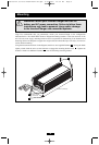
Features
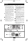
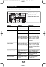
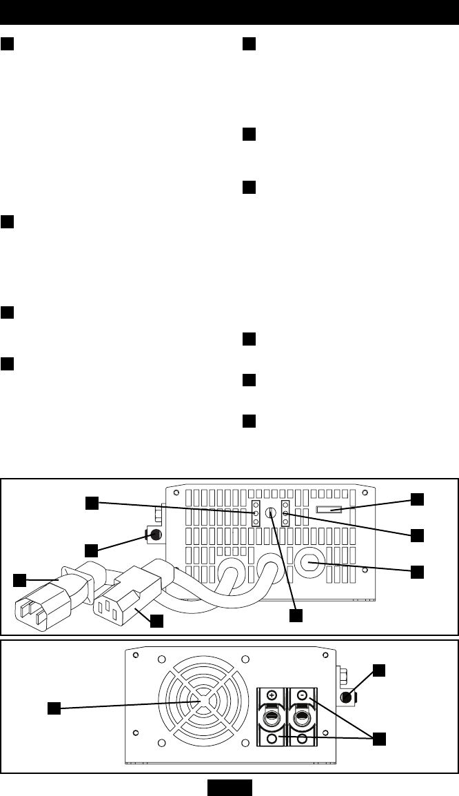
Operating Mode Switch: controls Inverter/
Charger operation. When this switch is set to
“AUTO”, connected equipment receives
constant, uninterrupted utility AC power,
with simultaneous charging of connected
batteries. The “CHARGE ONLY” setting
prevents unwanted battery rundown when
there is no need for battery backup.
Connected batteries are recharged. When the
Operating Mode Switch is set to “DC OFF”,
both the inverter and the battery charger are
shut off. However, the unit will still pass
utility AC power to connected equipment if
it is plugged into an AC outlet.
“OPERATION” Indicator Lights: These
intuitive “traffic light” signals show whether
the Inverter/Charger is operating from AC
line power or from DC battery power. They
also signal an alert if the connected
equipment load is too high. See the
Operation section for details.
“BATTERY” Indicator Lights: These
“traffic light” signals show the approximate
charge level of your battery. See the
Operation section for details.
AC Input: IEC 60320 C14 connects the
Inverter/Charger to a source of utility- or
generator-supplied AC power. See the AC
Connection section for instructions.
AC Output: IEC 60320 C13 permits
connection of equipment that would
normally be plugged into a utility outlet.
Note: The unit will always pass AC power
to connected equipment if plugged into a
live AC outlet, regardless of the position of
the Operating Mode Switch.
Circuit Breaker: Protects the Inverter/
Charger against damage due to overload. See
the Operation section for resetting
instructions.
Low Line Adjustment: Sets the AC input
voltage at which the Inverter/Charger will
switch from utility AC power to inverted
battery power, allowing you to optimize
operation in areas with frequent brownouts.
If the dial is set fully counterclockwise, the
unit will allow AC input to drop to
approximately 160 V before switching to
inverter mode. Note: The unit will continue
to pass lower-voltage AC utility power to
connected equipment until the unit
switches to inverter mode.
DC Connectors: Connect to your battery
terminals with user-supplied cabling. See
Battery Connection section for instructions.
Cooling Fan: Regulates internal
temperature and prolongs equipment service
life.
Main Ground Lug: Grounds the Inverter/
Charger to earth ground or vehicle
grounding system. See Battery Connection
section for instructions.
1
2
3
4
5
6
7
8
9
10
1
2
3
4
6
7
10
8
9
10
5
200705102 93-2678 APSX700HF OM.qxd 8/30/2007 12:34 PM Page 3