


unigreen 11
NEVER USE THE CARDAN TRANSMISSION IF THE FOLLOWING
PROTECTIVE COVERS ARE MISSING:
a) TRACTOR POWER-TAKEOFF PROTECTIVE COVER
b) CARDAN SHAFT PROTECTIVE COVER
c) FIXED PROTECTIVE COVER ON THE PUMP SHAFT
d) Hook any safety chains to solid anchor points
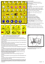
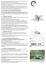
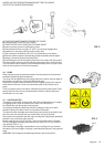
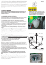
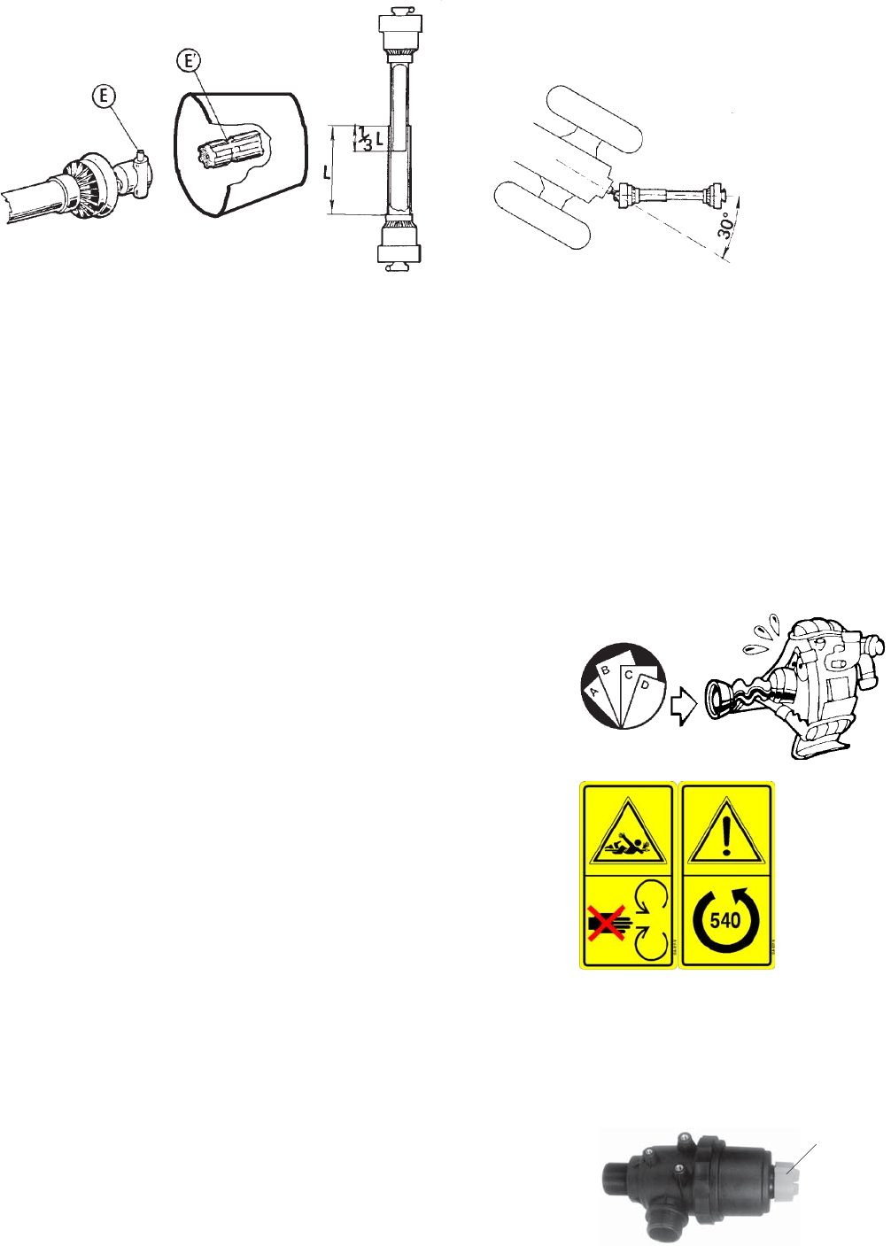
e) Check that the button or ringnut “E” (FIG. 2) is correctly engaged and
blocked both on the pump side and on the tractor side.
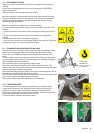
f) Don’t exceed an inclination of 30°-35° in any direction for any reason
g) With the machine stopped, periodically grease the spiders and the pipes,
keeping the connecting zone particularly clean.
h) Avoid letting the end of the cardan shaft come into contact with the ground
with the machine stopped; use the relevant support on some versions for this,
if your machine has no support, hook the external safety chain to a part of the
frame of the machine (ex. control unit support).
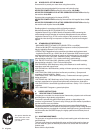
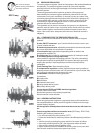
4.6 PUMP
When using the pump scrupulously observe the instructions in the enclosed
handbook supplied by the manufacturer.
The pump can be identified by the ratings plate on the same; the main data on
the pressure and delivery are easy to find on this plate.
Normally the pumps mustn’t exceed 550 RPM; a higher speed won’t improve
performance but there is a risk of compromising the life and safety of the
pump.
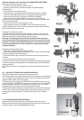
There is a safety valve on the pump, calibrated to prevent overpressure. Don’t
tamper with this valve for any reason and don’t block or obstruct the pipes
connected to it in any way.
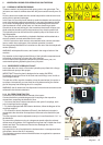
4.7 SUCTION FILTER
The sprayer is fitted with a suction filter with filter cartridges that have roughly
a 50-gauge mesh, which is equivalent to a hole of 0.4 at 0.35 mm.
An efficient filter lets the sprayer work properly.
You should periodically check that the filter cartridge is clean, this check
should be done more often if there are impurities in the liquid.
To inspect the filter cartridge wear rubber acid-proof gloves as the liquid in the
filter can come into contact with your hands when you open the filter.
Don’t perform this operation with the pump running as the depression produced
blocks the cover preventing the removal.
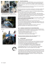
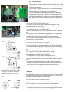
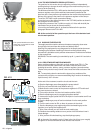
Before removing the cover of the filter, make sure that the same is isolated
from the tubing by unscrewing the relevant rear valve (FIG. N° 3) or on the 3-
way deviator (FIG. N° 11).
After washing the cartridge, reassemble the cover making sure you connect
the same to the circuit again, using the valves described above in the opposite
order.
WARNING!: Don’t disperse the washing residues in the environment!!
FIG. 3
Valve
FIG. 2