


before installing or removing blade.
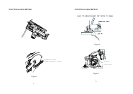
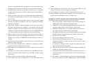
1. To remove the blade (Fig.8, press the shaft lock so that the blade cannot
revolve and use the hex wrench to loosen the bolt clock-wise. Then remove the
bolt, outer flange and blade.
2. To install the blade, follow the removal procedure in reverse.
BE SURE TO TIGHTEN THE BOLT SECURELY
3. Hold the work spindle still by pressing the spindle lock down and loosen the
screw. Remove washer and clamping.
4. Swing swivel guard backwards, hold it still, and remove the saw blade from
the clamping flange. Fit the new saw blade by following the above steps in the
reverse order. The arrow on the saw-blade must point in the same direction as
the direction of rotation arrow.
CAUTION:
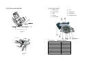
BE SURE THE BLADE IS INSTALLED WITH TEETH POINTING UP
AT THE FRONT OF THE TOOL.(SEE FIGURE 8)
1) Nut
2) Outer flange
3) Blade
4) Inner flange
5) Gauge
6) Hex Wrench Storage
When not in use, the hex wrench can be conveniently stored.
CAUTION: Always be sure that he tool is switched off and battery cartridge is
removed before any adjustment is attempted.
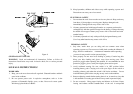
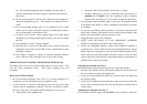
ADJUSTING DEPTH OF CUT
Loosen the lever on the depth guide and move the base down.
At the desired depth of cut, secure the base by tightening the lever.
CAUTION:
Use a shallow depth of cut, when cutting thin work pieces for cleaner, safer cuts.
After adjusting the depth of cut, always tighten the lever securely.
OPERATION
1. Switch on the tool and apply to the material with the front edge of guide
plate.
2. Align the tool with the parallel guide or a line drawn by hand prior to
operation.
3. Hold the tool firmly by both handles.
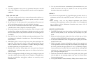
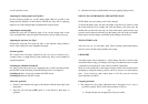
BEVEL CUTTING
Loosen the screw on the bevel scale plate on the front of the base. Set for
desired angle (0-45°) by tilting accordingly, then tighten the swing nut securely.
CAUTION:
Cutting work pieces that exceed the maximum cutting depth will result in
overload of the battery. Overheating and smoke emitting from the battery
will occur.
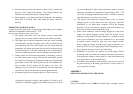
Hints
When sawing along a line use the cutting information shown in the
window according to the cutting angle.
Right-angled cut –indicator on 0-45°.
For bevel cuts the guide (i. e. parallel guide, ridge) must be applied
shifted to scale (carry out a test cut). The parallel guide allows a
maximum cutting length of 5.91 inches/150 mm and maximum cutting
depth 1.97 inches/50 mm.
For wider cuts use a guide bar (accessory) or lead the tool along a fixed
17 18