


16 ProSpray 3.21
GB
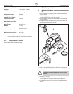
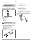
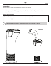
Repairs at the unit
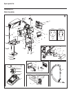
18. Slide the top of the piston (3) into the T-slot (9) on the slider
assembly (4).
19. Position the pump manifold (2) underneath the gear unit
housing and push up until it rests against the gear unit
housing.
20. Attach pump manifold (2) to the gear unit housing.
21. Screw pump manifold (2) tightly to gear unit housing.
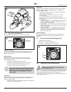
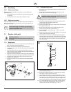
22. Lubricate O-ring (Fig. 11, Item 6) between pump manifold (2)
and inlet valve housing with machine grease. Screw inlet valve
housing to the pump manifold.
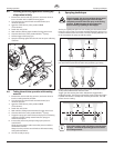
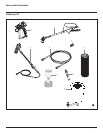
23. Insert the elbow on the siphon assembly into the bottom of
the pusher stem housing. Push the retaining clip up into the
groove inside the foot valve housing to secure the siphon
assembly in position. Place the return tube over the return
tube tting and secure with the clip.
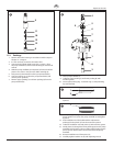
24. Install front cover.
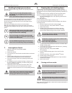
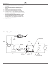
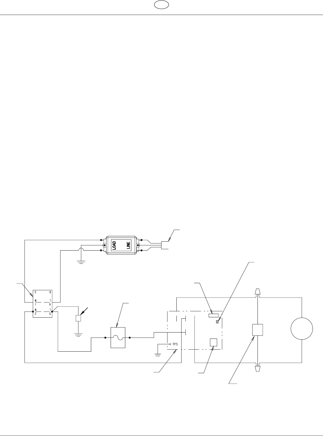
11.4 ProSpray 3.21 connection diagram
Capacitor Assembly
P/N 0522054
Black
White
Blue
Black
P/N 0516360
P/N 0516360
Motor
Red (+)
Black (-)
Red (+)
Black (-)
Potentiometer
Power Cord
EMI Filter
Ground
Ground
PC Board
Assembly
Pressure
Transducer
Black
Red
WhiteGray
Circuit
Breaker
Switch
L.E.D.
Black Black