


10
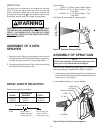
ASSEMBLY OF A NEW
SPRAYER
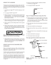
1. Screw the return fitting into the elbow on the front side
of the paint pump. Both fittings should be hand tight only,
but tight enough to prevent air from being drawn in.
2. Screw the paint hose, wrench tight, onto the outlet fitting
on the front side of the paint pump.
SPRAY GUN TIP SELECTION
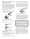
Select a spray gun tip as follows:
LACQUERS &
STAINS ENAMELS LATEX
0153315 0153317 0153319
0153415 0153417 0153419
Example 0153 3 19
0153 3 19
Prefix Spray Pattern Size of Spray Tip
Width In Degrees Holes In Inches
(In this case, 30°) (In this case,.019")
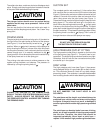
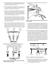
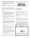
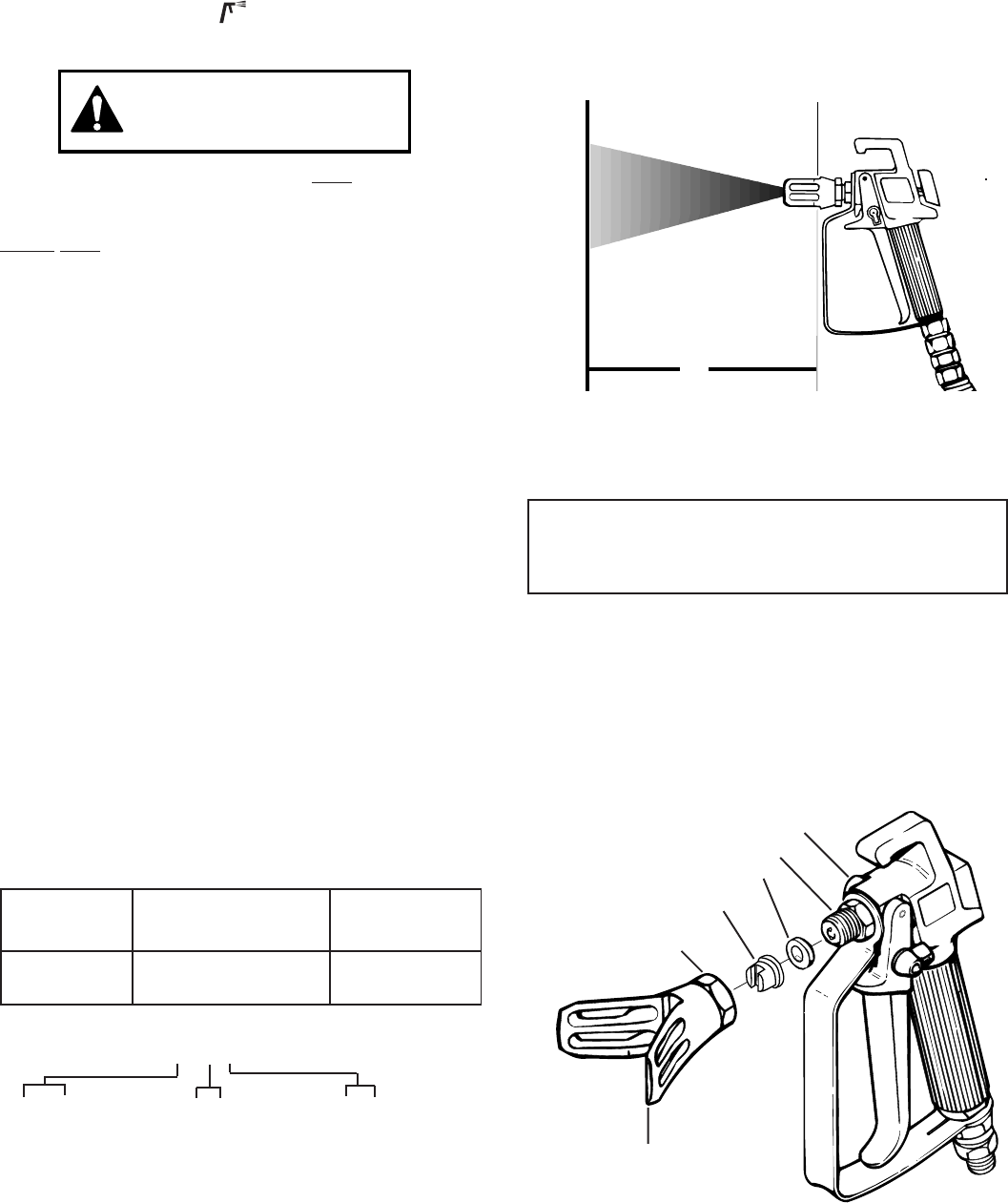
Figure 3.-Spray Tip Assembly Sequence.
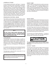
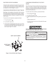
Spray Pattern
Width = 2 x Spray Pattern Width Number
e.g. 0153319 = 2 X 3 = 6” Spray Pattern 1 Foot
from Work
0153419= 2 x 4 = 8” Spray Pattern 1 Foot
from Work
See Figure 2 for example of a spray pattern.
WIDTH OF SPRAY
PATTERN IN INCHES
1'
ASSEMBLY OF SPRAY GUN
After you have selected the proper spray tip, assemble it
onto the spray gun as explained in Steps 1 through 4.
1. lnsert the spray tip and sealing washer into the tip guard
so that the flats of the spray tip are seated perfectly into
the tip guard. See Figure 3.
2. Hand tighten the tip nut onto the diffuser.
NOTE
Follow the Assembly Instructions that came with
your gun if it is a brand other than Wagner.
SEALING WASHER
SPRAY TIP
DIFFUSER
SPRAY GUN
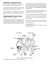
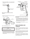
The spray gun is connected to the sprayer by the paint
hose. The gun will spray when the unit is running, the
suction and return tubes are in the spray material, the
priming knob is turned to the pressure control valve
is adjusted, and the spray gun trigger is pulled back.
WARNING
THE SPRAYTECH ED1150 PUMP IS NOT COMPATIBLE
FOR USE WITH HALOGENATED HYDROCARBON SOL-
VENTS. THE WAGNER G-05, G-09 AND G-10 GUNS
MUST NOT BE USED WITH HALOGENATED HYDRO-
CARBON SOLVENTS.
Figure 2.-Example of Spray Pattern
SPRAY GUN
TIP NUT
TIP GUARD