17
When the diaphragm or diaphragm parts have to be re-
placed, proceed as follows:
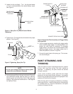
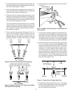
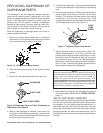
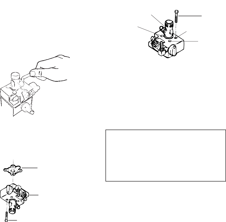
1. Remove the 4 paint pump screws with a 6 millimeter
alIen wrench. As you remove the 4 screws, also remove
the 4 washers that may remain in the holes.
Figure 15. - Remove paint pump screws
2. Take the paint pump housing off the hydraulic pump
housing.
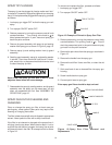
3. Remove the old diaphragm and the old insert ring.
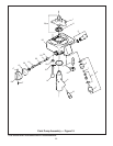
Figure 16.-Diaphragm Parts and Their Relationship to
Other Parts of the Sprayer.
4. When a new diaphragm is installed, a new insert ring
(see Figure 16) should also be installed. Install the new
Insert. Be sure to put the flat surface of the insert ring into
the flat surface of the paint pump.
REPLACING DIAPHRAGM OR
DIAPHRAGM PARTS
The diaphragm is the only separation between the paint
pump and the hydraulic pump. It pumps paint, but it also
serves as a gasket between the hydraulic pump and paint
pump. If the diaphragm membrane ruptures, paint will
probably get into the hydraulic housing. If adequately
cleaned up soon enough, the parts (bearing, piston, etc.)
can be saved. If the hydraulic housing is not cleaned up
soon enough, you may have internal freeze-up.
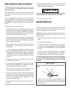
5. Install the new diaphragm. Put the membrane stem and
nut side of the diaphragm in the hydraulic pump housing
hole.
6. Put the paint pump back on. Before installing the 4 paint
pump screws, put Anti-Seize Lubricant on the screw
threads. (This prevents the steel screws from galling
and seizing in the aluminum hydraulic pump). Now
install the 4 new paint pump washers and 4 screws using
a 6 millimeter allen wrench (see Figure 17).
8. After replacing or repairing the diaphragm, the sprayer
will have to be bled. See Number 9, “BLEED THE AIR,”
page 12.
USE OF ANTI-SEIZE LUBRICANT
You should use Anti-Seize Lubricant (part number 0093930)
any time you are screwing dissimilar metal thread connec-
tions together. On your sprayer these connections are; (1)
steel outlet valve into paint pump, (2) steel inlet valve into
paint pump, (3) steel priming valve into paint pump, (4) steel
paint pump screws into aluminum hydraulic pump, and (6)
steel pressure control valve into iron pressure vessel/hydrau-
lic pump.
PAINT PUMP SCREW
DIAPHRAGM
PAINT PUMP
NOTE:
Improper torquining sequence of the paint pump screws may
cause damage to diaphragm and inefficient pump performance.
Proper torque also prevents hydraulic oil from leaking out
between the paint pump and the hydraulic housing. It is
recommended that a new unit be re-torqued after the first 20
hours of operation. Thereafter, tighten the paint pump screws
after every 3 or 4 operations. One lockwasher should always be
used with each of the four paint pump screws.
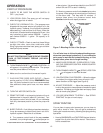
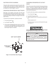
7. Tighten opposite screws in turn as shown. (A-B, C-D).
Tighten screws evenly to 13-15 ft lbs. (156-180 inch-
pounds) torque. Begin at screw A tightening to 10 ft lbs.
continue to screw D. Repeat this step until all screws
have attained a torque of 10 ft. lbs. Repeat sequence
tightening to 14 ft lbs. and repeat one more time tighten-
ing to 14 ft lbs. Following this tightening sequence will
assure proper seating of the diaphgram.
Figure 17-Tightening Paint Pump Screws.
D
C
B
PAINT
PUMP
SCREW
A
©1995 WAGNER SPRAY TECH CORPORATION. ALL RIGHTS RESERVED.


