


GB
26
WallPerfect W 665 I-Spray
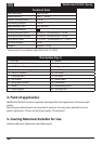
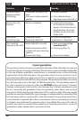
15. Taking Out of Operation and Cleaning
Proper cleaning is the prerequisite for problem-free operation of the paint application
device. No warranty claims are accepted in case of improper or no cleaning.
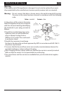
Turn the machine o. 1)
Divide the spray gun. Press the hook (Fig. 5 "click") slightly downwards. Turn the gun 2)
front part and gun rear part against each other.
Screw of the container and empty it. Pull out the suction tube with container seal.3)
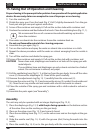
Preclean the container and feed tube with a brush. Clean the ventilating bore (Fig. 11, 1).
4)
i
We recommend the use of a common household washing-up brush to
clean the container.
Pour water or solvent into the container. Screw the container back on.
5)
Do not use ammable materials for cleaning purposes.
Assemble the gun again (Fig. 5).6)
Turn on the machine and spray the water or solvent into a container or a cloth.7)
Repeat the above procedure until the water or solvent emerging from the nozzle is 8)
clear.
Turn o the machine and divide the spray gun.9)
Screw of the container and empty it. Pull out the suction tub with container seal.10)
CAUTION! Never clean seals, diaphragm and nozzle or air holes of the spray gun with
metal objects.
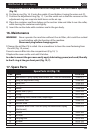
The ventilation hose and diaphragm are only solvent-resistant to a limited
extent. Do not immerse in solvent, only wipe.
Pull the ventilating hose (Fig.12, 1) at the top from the gun body. Screw o the valve 11)
cover (2). Remove the diaphragm (3). Clean all the parts carefully.
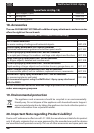
Remove the adjustment ring (g. 13, 1) carefully from the union nut (2).12)
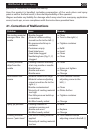
Unscrew the union nut (Fig. 13, 2) and remove the air cap (3), nozzle (4) and nozzle seal
13)
(5). Clean the air cap, nozzle seal and nozzle with a brush and water or solvent.
Clean the outside of the spray gun and container with a cloth soaked in solvent or
14)
water.
Assemble the parts again (see “Assembly”).15)
Assembly
The unit may only be operated with an integer diaphragm (Fig. 12, 3).
Place the diaphragm (Fig. 12, 3) 1) with the pin facing upwards on the bottom section
of the valve. Also see the marking on the gun body.
Place on the valve cover 2) (Fig. 12, 2) and screw it closed.
Place the ventilating hose 3) (Fig. 12, 1) on the valve cover and on the nipple at the gun
body.
Slide the nozzle seal (Fig. 14, 5) with the groove (slot) facing forwards into the
4)
nozzle.
Place the nozzle (g. 14, 4) on to the gun body with the recess facing downwards.
5)