


TROUBLESHOOTING
For assistance with your tool, visit our website at www.porter-cable.com for a list of service centers, or
call the Porter-Cable Customer Care Center at (888) 848-5175.
MAINTENANCE
KEEP TOOL CLEAN. Periodically blow out all air passages with dry compressed air. All plastic parts should
be cleaned with a soft damp cloth. NEVER use solvents to clean plastic parts. They could possibly dissolve or
otherwise damage the material.
When making cuts on all four edges of the workpiece, make the first cut on the end of the piece across the
grain. If chipping of wood occurs at the end of a cut, it will be removed when making the next cut parallel
with the grain.
Periodically wipe columns clean with a dry cloth. DO NOT lubricate the columns.
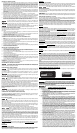
VARIABLE SPEED CONTROL (690LRVS)
This router is equipped with a variable speed control (A) Fig. 19 with an infinite number of speeds between
10,000 and 27,000 RPM.
Adjust the speed by turning the speed control knob (A), labeled 1 through 4, with 1 being the slowest speed
and 4 being the highest.
A
B
Fig. 1
A
C
Fig. 15
C
Fig. 7
Fig. 9
Fig. 10
Fig. 14
Fig. 2
Fig. 3
A
F
C
B
C
Fig. 4
A
Fig. 5
A
B
Fig. 6
A
B
A
B
A
C
Fig. 11
A
B
Fig. 12
A
B
A
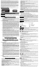
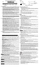
DO NOT attempt to increase the plunge travel by readjusting the stop nut. Increasing
the travel beyond 2-1/2" can cause the mechanism to jam.
1. While holding the lever in the upright position (Fig. 13), remove the retaining screw. Continue
to hold the lever through the remaining steps.
2. Use an 1/8" hex wrench (A) Fig. 14 (not furnished) to turn the adjustment screw counter-clock-
wise approximately 1/2 turn.
3. Move the lever to the desired locked position and tighten the adjustment screw.
4. Remove the hex wrench and replace the retaining screw.
ADJUSTING THE PLUNGE LOCKING LEVER
You can adjust the plunge-locking mechanism to reposition the lever (in the locked position), or to
compensate for wear.
ATTACHING THE POWER UNIT TO THE “D” HANDLE BASE
1. Loosen the clamp screw (A) Fig. 15 to set the power unit in the base unit.
2. With the motor switch (C) Fig. 15 in the “ON” position, insert the motor unit into the base align-
ing the lower pin (B) with the groove in the base.
3. Rotate the motor unit into the base CLOCKWISE until the motor switch (A) Fig. 16 is directly
above the knob handle (B).
4. Connect the motor unit cord to the outlet in handle (C) Fig. 16.
5. Continue rotating the motor unit into the base until upper guide pins set rigidly into base.
6. Tighten the clamp screw firmly.
ADJUSTING THE DEPTH OF CUT
1. Loosen the clamp screw (A) Fig. 17.
2. Hold the base (E) and turn the motor unit (F) Fig. 17 counter-clockwise until the tip of the bit is
above the bottom of the base.
3. Set the router on a flat surface.
4. Turn the motor unit (F) Fig. 17 clockwise until bit touches the wood surface.
5. Tighten the clamp screw (A) Fig. 17.
6. Rotate the depth adjusting ring (B) Fig. 17 until the zero-line (C) is opposite the index line (D)
on the housing.
7. Loosen the clamp screw (A) Fig. 17.
8. Tip the router so that the bit is clear of the wood surface. Turn the motor unit (F) Fig. 17 clock-
wise until the index line (D) on the motor housing reaches the desired depth indicated on the
ring.
9. Tighten the clamp screw (A) Fig. 17 firmly.
NOTE: Setting the index line to 1/4" on the ring means the cutting edge of the bit is exposed 1/4"
below the base
.
CONNECTING TO POWER SOURCE
Before connecting tool to power source, check to see that the switch is in the "OFF"
position. Also, check the power circuit to see that it is the same as that shown on specification
plate of the tool.
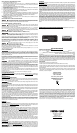
STARTING AND STOPPING THE MOTOR
Before starting the tool, clear the work area of all foreign objects. Also keep firm grip
on tool to resist starting torque.
To start the tool, move the rocker switch (A) Fig. 18 to the “ON” or “1” position. To stop the tool,
move the rocker switch to the “OFF” or “O” position.
To avoid personal injury and/or damage to finished work, always allow the power unit
to come to a COMPLETE STOP before putting the tool down.
STARTING AND STOPPING THE MOTOR - “D” HANDLE
Before starting the tool, clear the work area of all foreign objects. Also keep a firm grip
on the tool to resist starting torque.
USING THE TOOL
Check to see that the motor unit power cord (C) Fig. 16 is plugged into the handle, and that the switch
(A) on the motor is set to the “ON” position. The starting and stopping of the motor is then controlled by
pressing and releasing the trigger switch (D) Fig. 16 in the handle of the base.
To allow the tool to run without continually pressing the trigger, press the trigger (D) into the handle and
engage the switch locking button (E) on the side of the handle. While holding the button in, slowly release
the trigger. To stop the tool, squeeze the trigger into the handle and release.
To avoid injury and/or damage to finished work, always allow motor to come to a COMPLETE
STOP before putting the tool down.
Always be sure the work is rigidly clamped or otherwise secured before making a cut.
When routing the edges, hold the router firmly down and against the work with both guiding knobs.
Since the cutter rotates clockwise (when viewing router from top), the router should be moved from left to
right as you stand facing the work. When working on the inside of a template, move the router in a clockwise
direction.
When working on the outside of a template, move the router in a counter- clockwise direction.
Avoid “Climb-Cutting” (cutting in direction opposite that shown in Fig. 20). “Climb-Cutting”
increases the chance for loss of control resulting in possible injury. When “Climb-Cutting” is required
(backing around a corner), exercise extreme caution to maintain control of router.
The speed and depth of cut will depend largely on the workpiece. Keep the cutting pressure constant but
do not crowd the router so the motor speed slows excessively. On exceptionally hard woods or problem
materials, more than one pass at various settings may be necessary to get the desired depth of cut.
LUBRICATION
This tool has been lubricated with a suffi cient amount of high grade lubricant for the life of the unit under normal
operating conditions. No further lubrication is necessary.
BRUSH INSPECTION (If applicable)
For your continued safety and electrical protection, brush inspection and replacement on this tool should ONLY
be performed by a Porter-Cable Factory Service Center or a Porter-Cable Authorized Warranty Service Center.
At approximately 100 hours of use, take or send your tool to your nearest Porter-Cable Factory Service Center
or a Porter-Cable Authorized Warranty Service Center to be thoroughly cleaned and inspected. Have worn parts
replaced and lubricated with fresh lubricant. Have new brushes installed, and test the tool for performance.
Any loss of power before the above maintenance check may indicate the need for immediate servicing of your
tool. DO NOT CONTINUE TO OPERATE TOOL UNDER THIS CONDITION. If proper operating voltage is pres-
ent, return your tool to the service station for immediate service.
D
E
B
D
C
1/2"
B
A
C
D
E
B
A
Fig. 16
F
B
D
C
E
A
Fig. 18
Fig. 13
Fig. 19
Fig.8
A
D
B
A
Fig. 17
E
Fig. 20
Wear ANSI Z87.1 safety glasses while using compressed air.
FAILURE TO START
Should your tool fail to start, check to make sure the prongs on the cord plug are making good contact in the
outlet. Also, check for blown fuses or open circuit breakers in the line.
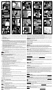
REMOVING THE MOTOR
1. Remove the clamp screw (A) Fig. 5, flat washer (B), lock washer (C), and clamp-locking nut (A)
Fig. 6.
2. Insert the hex wrench (A) Fig. 8 to contact the locking plate. Tap lightly to release and remove
the locking plate.
3. Slide the motor out of the base.
4. Reattach the clamp screw, lock washer, flat washer, locking plate and clamp locking nut to the
base and tighten lightly.
ADJUSTING THE PLUNGE BASE
1. Loosen the depth rod locking knob (A) Fig. 9, and the depth indicator knob (D), allowing the
depth rod (E) to contact one of the turret stops (B). Normally the deepest desired cut is set with
the depth rod resting on the shortest turret stop (A) Fig. 10. The other two fixed stops (B) Fig. 10
provide reduced cutting depths of 1/4" and 1/2" respectively. You can adjust the three stops (C)
Fig. 10 to any desired height. You can utilize any combination of fixed and/or adjustable stops
to achieve the desired depths required for a particular job.
2. Release the plunge mechanism by pulling the locking lever (A) Fig. 9 to the left. Lower the
plunge mechanism until the router bit touches the work surface. Release the lever and push it
to the right to lock the mechanism in this position.
3. Tighten the depth-rod locking knob.
4. Position the depth indicator (A) Fig. 11 at the “0” position and tighten the knob.
5. Loosen depth-rod locking knob (A) Fig 9. Raise the indicator until it aligns with the gradua-
tion representing the desired depth of plunge. (The example in Fig. 12 shows setting for 1"
plunge.)
6. Turn the lower travel-limiting nut (A) Fig. 12 until it is approximately 1/4" above the top of the
the plunge housing. While holding the lower nut, turn the upper nut (B) until it “jams” against
the lower nut (A) Fig. 12.
Jam the travel-limiting nuts together to prevent movement (caused by vibration) which
could prevent full bit retraction.
Set the travel limiting nuts so that bit can be retracted into the base of the router, clear
of the workpiece.
SERVICE
REPLACEMENT PARTS
Use only identical replacement parts. For a parts list or to order parts, visit our website at servicenet.porter-
cable.com. You can also order parts from your nearest Porter-Cable Factory Service Center or Porter-Cable
Authorized Warranty Service Center. Or, you can call our Customer Care Center at (888) 848-5175.
SERVICE AND REPAIRS
All quality tools will eventually require servicing and/or replacement of parts. For information about Porter-
Cable, its factory service centers or authorized warranty service centers, visit our website at www.porter-cable.
com or call our Customer Care Center at (888) 848-5175. All repairs made by our service centers are fully
guaranteed against defective material and workmanship. We cannot guarantee repairs made or attempted by
others.
You can also write to us for information at PORTER-CABLE, 4825 Highway 45 North, Jackson, Tennessee
38305 - Attention: Product Service. Be sure to include all of the information shown on the nameplate of your
tool (model number, type, serial number, etc.).
ACCESSORIES
A complete line of accessories is available from your Porter-Cable Factory Service Center or a Porter-Cable
Authorized Warranty Service Center. Please visit our Web Site www.porter-cable.com for a catalog or for the
name of your nearest supplier.
Since accessories other than those offered by Porter-Cable have not been tested with this
product, use of such accessories could be hazardous. For safest operation, only Porter-Cable recommended
accessories should be used with this product.
WARRANTY
To register your tool for warranty service visit our website at
www.porter-cable.com
.