


16
damaged.
5. Inspect bearings for damage and smooth opera-
tion, Replace if faulty.
6. Install the bearing in the idler wheel. Install the idler
wheel on the idler shaft.
7. Install the screw, spring washer and washer in the
idler shaft.
8. Install the blade (see Changing blades).
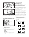
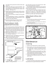
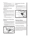
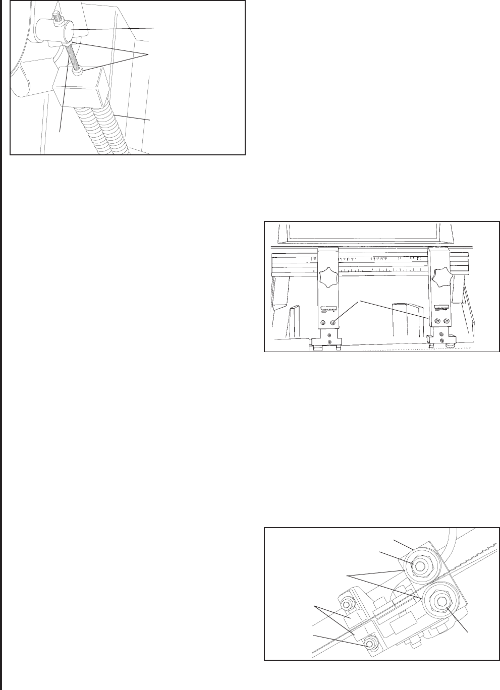
Adjusting the Blade Guides
The cut-off saw has adjustable blade guide supports
(see figure 17). The blade guide supports allow you to
set the blade guides for varying widths of workpieces.
To make accurate cuts and prolong blade life, the
blade guide supports should be set to just clear the
workpiece to be cut.
Figure 17: Blade guide supports
1. Loosen the knob on the blade guide support and
slide the guide left or right as required. Repeat for
the other blade guide.
2. Set the blade guide supports as required to accom-
modate the width/diameter of the workpiece. The
blade guides should be positioned so the guides do
not contact the workpiece as the saw head moves
downward through the workpiece.
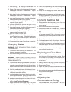
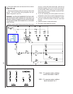
Replacement of Carbide
Blade Guide
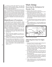
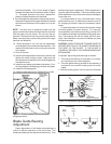
Figure 16: Counterbalance spring adjustment
Counterbalance
Spring
Adjustment Nuts
Pivot
Threaded
Rod
Blade Guide
Supports
Concentric Bushing
Eccentric
Bushing
Blade Guide Bearings
Cap Screw
(Typical)
Carbide
Guides (2)
Cap Screw
(Typical)
Figure 18: Carbide blade guides and guide bearings
used to adjust the amount of down force the saw head
puts on the workpiece when the feed rate control valve
is fully open.
1. Raise the saw arm to its full upright position and
lock it in position.
2. To adjust the tension on the spring, loosen the two
nuts on the threaded rod of the spring pivot post.
Adjust the tension as required.
3. Tighten the two nuts against the pivot post.
4. The saw can now be returned to service.
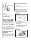
Replacing the Drive Wheel
1. Remove the blade (see Changing Blades).
2. Remove the screw, spring washer, and washer from
the speed reducer shaft.
3. Pull the wheel from the speed reducer shaft. Re-
move the drive key from the speed reducer shaft.
4. Inspection: Examine drive edge and shoulder of
the wheel for damage. Replace the wheel if dam-
aged.
5. Install the key in the keyway in the speed reducer
shaft. Align the keyway in the wheel with the key in
the speed reducer shaft. Reinstall the wheel on the
speed reducer shaft.
6. Install the screw, spring washer and washer in the
end of the speed reducer shaft.
7. Install the blade (see Changing Blades).
Replacing Idler Wheel or
Idler Bearing
1. Remove the saw blade (see Changing Blades).
2. Remove the screw, spring washer, and washer from
the idler shaft.
3. Remove the idler wheel. Remove the bearing from
the idler wheel.
4. Inspection: Examine the drive edge and shoulder
of the idler wheel for damage. Replace the wheel if