


8
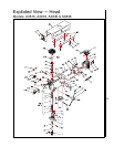
Operating Precautions
The following operating and safety precautions must
be observed in order to avoid harm to the operator
or damage to the drill press.
1. The head assembly must be locked to the
column so the thrust produced by drilling will
not force the head assembly up the column.
2. The work table must be locked to the column
so it will not be forced down the column.
3. Be sure the belt is tightened to the proper
tension.
4. DO NOT start to drill the workpiece until
making certain the workpiece is held down
securely.
5. MAKE SURE THE DRIVE MOTOR IS RUN-
NING BEFORE turning the speed control
handwheel in either direction.
6. Point of operation protection is required for
maximum safety. This remains the responsibil-
ity of the user/purchaser since conditions differ
between jobs.
7. Make sure the drill is secured in the spindle or
check before attempting to use the drill press.
8. Make sure the spindle taper is clean and free
of burrs, scoring, and galling to assure maxi-
mum gripping.
Drilling Recommendations
Speeds for Drilling
The speed of a drill is usually measured in terms of
the rate at which the outer periphery of the tool
moves in relation to the work being drilled. The
common term for this is Surface Feet per Minute
(SFM). The relationship of SFM is expressed in the
following formulas:
SFM = 0.26 X rpm X Drill Diameter (in inches)
RPM = 3.8 x ________SFM__________
Drill diameter (in inches)
In general, the higher the speed the shorter the drill
life. Operating at the low end of the speed range for
a particular material will result in longer life. The
most efficient speed for operating a drill depends on
many variables:
1. Composition and hardness of material.
2. Depth of the hole.
3. Efficiency of the cutting fluid.
4. Type and condition of the drilling machine.
5. Desired quality of the hole.
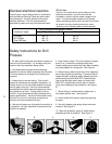
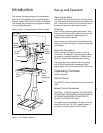
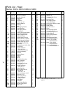
Figure 2. Operating Controls
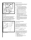
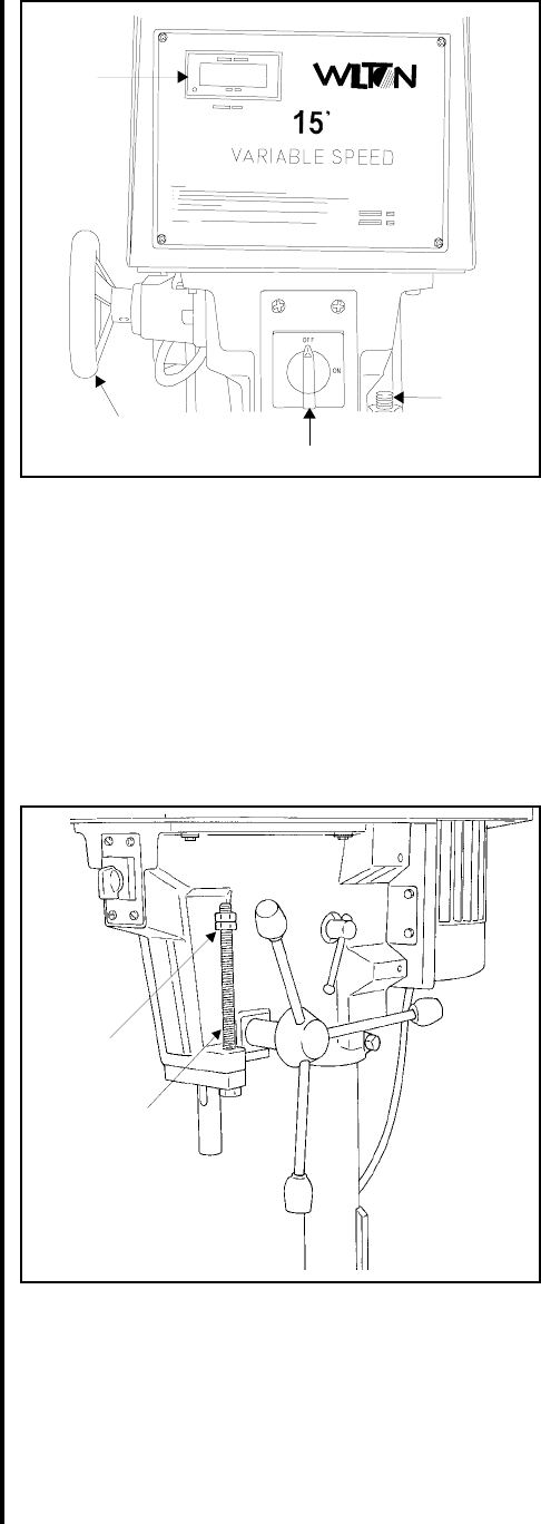
Depth Stop
A drilling depth stop (refer to Figure 3) is provided on
the right side of the drill head. The depth stop
consists of a threaded rod with depth setting jam
nuts. The front side of the threaded rod has a depth
scale. The jam nuts are loosened and moved to the
desired depth on the scale. The upper jam nut is
then tightened against the lower nut.
Figure 3. Depth Stop
LED
Speed
Display
Speed control
handwheel
On/Off switch
Depth
stop
Jam
nuts
Depth scale
(on threaded
rod)