


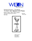

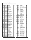
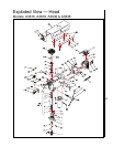
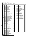

9
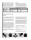
6. Difficulty of set-up.
Indication of Extreme Speeds and Feeds
A drill that splits up the web is evidence of too much
feed or insufficient tip clearance at the center as a
result of improper grinding. The rapid wearing away
of the extreme outer corners of the cutting edges
indicates that the speed is too high. A drill chipping
or braking out at the cutting edges indicates that
either the feed is too heavy or the drill has been
ground with too much tip clearance.
Speeds for High Speed Steel Drills
Speed
Material In SFM
Alloy Steel — 300 to 400 Brinell .....................20 - 30
Stainless Steel ................................................30 - 40
Automotive Steel Forgings .............................40 - 50
Tool Steel, 1.2C ..............................................50 - 60
Steel, .4C to .5C .............................................70 - 80
Mild Machinery Steel, .2C to .3C .................. 80 - 110
Hard Chilled Cast Iron ....................................30 - 40
Medium Hard Cast Iron ................................70 - 100
Soft Cast Iron .............................................100 - 150
Malleable Iron .................................................80 - 90
High Nickel Steel or Monel .............................40 - 50
High Tensile Bronze ......................................70 -150
Ordinary Brass and Bronze ........................200 - 300
Aluminum and its Alloys .............................200 - 300
Magnesium and its Alloys ...........................250 - 400
Slate, Marble, and Stone .................................15 -25
Plastics and similar material (Bakelite).......100 - 150
Wood ...........................................................300 -400
Titanium Alloys ...............................................10 - 25
Titanium Alloy Sheet.......................................50 - 60
In cases where carbon steel drills are applicable, the
drill should be run at speeds of from 40 to 50
percent of those given above.
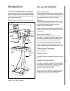
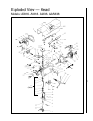
Maintenance
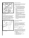
Replacement of Drive Belt
WARNING: MAKE SURE TO DISCONNECT
ELECTRICAL POWER TO THE DRILL PRESS TO
AVOID THE POSSIBILITY OF INADVERTENT
OPERATION AND EXPOSURE TO POTENTIALLY
LETHAL VOLTAGE LEVELS.
1. Start drill press. Set speed control to highest
speed. Stop drill press.
2. Disconnect electrical power to drill press.
3. Remove head cover.
4. Remove belt. (With speed control setting at the
highest speed, the belt should be loose enough
to remove.)
5. Install the replacement belt. Install the head
cover.
6. Connect electrical power to the drill press.
7. Operate the drill press to verify correct opera-
tion.
Replacement of Motor
WARNING: MAKE SURE TO DISCONNECT
ELECTRICAL POWER TO THE DRILL PRESS TO
AVOID THE POSSIBILITY OF INADVERTENT
OPERATION AND EXPOSURE TO POTENTIALLY
LETHAL VOLTAGE LEVELS.
1. Disconnect electrical power to drill press.
2. Remove drive belt (refer to Replacement of
Drive Belt).
3. Disconnect electrical wiring from motor junction
box.
4. Remove nuts and washers from bolts securing
motor to drill head. Remove motor.
5. Remove pulleys and related components from
motor shaft.
6. Install pulleys and related components on
replacement motor shaft.
7. Install motor on mounting bolts and secure with
nuts and washers.
8. Connect electrical wiring (refer to Wiring
Diagram section for wiring details).
9. Install drive belt (refer to Replacement of
Drive Belt).
10. Operate drill press to verify proper operation.
Lubrication
Following are lubrication recommendations for drill
press components.
1. Spindle pulley drive: Lubricate spindle splines
occasionally with light grease.
2. Quill, Table, and Column: Lubricate with light
film of oil.
3. Table lift rack: Lubricate regularly with SAE20
oil (clean rack with solvent before applying oil.)
4. Variable speed drive fork: Lubricate contact
points occasionally with grease.