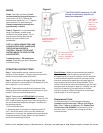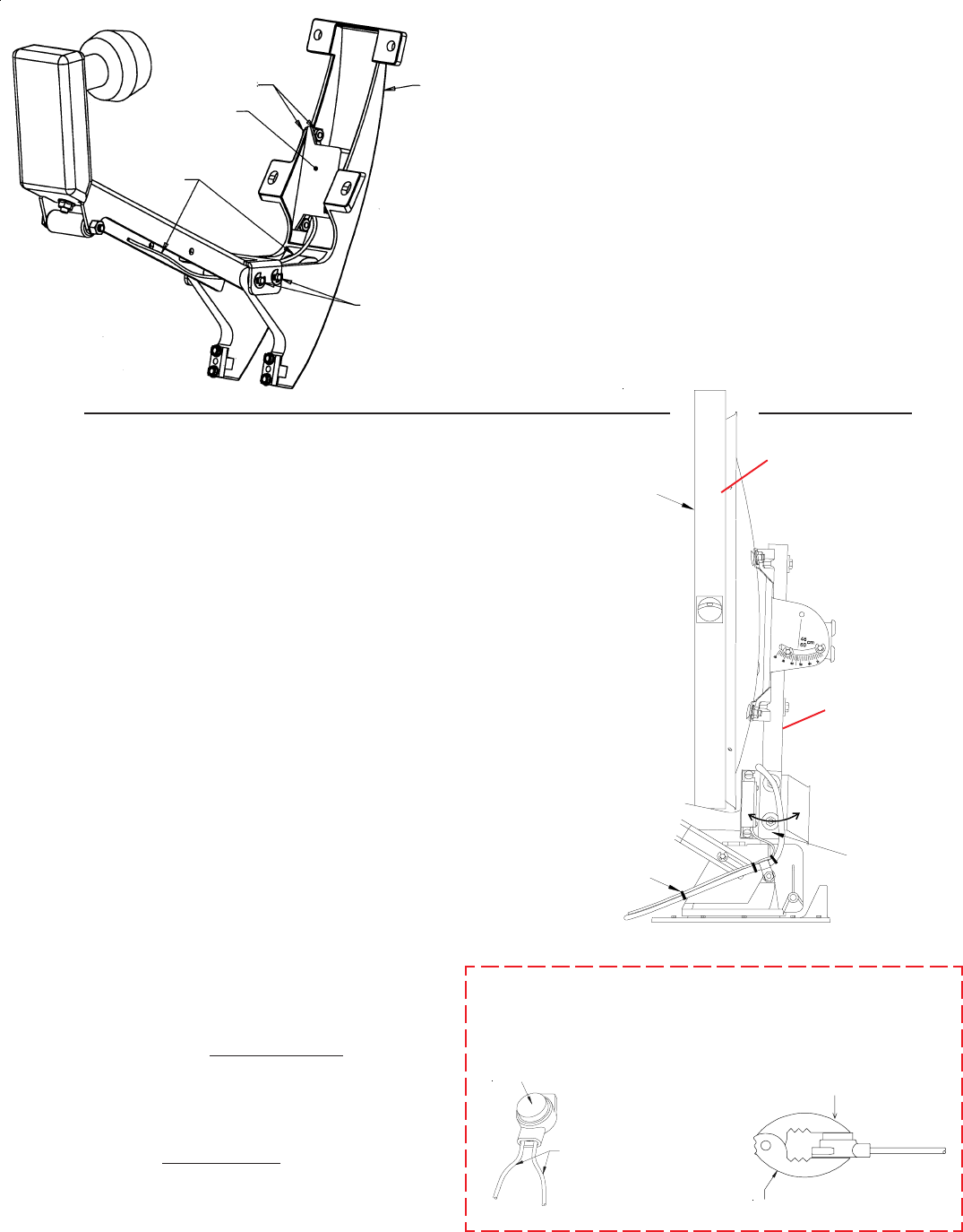
Step 4. Figure 5. Using cable ties attach sensor
cable to coax cable. Some RV manufacturers have
prewired their coaches with cable for the digital
elevation sensor. You will find these wires at the
appropriatly marked spot on roof. If not prewired, you
need to run wires from sensor through opening
(normally same entrance as coax) into coach
terminating them where you are installing the
wall plate display unit. It is recommended that the
display unit be mounted so you can read the
elevation numbers while cranking antenna to the
correct angle.
Step 5. Figure 5. Two persons will be required for
this step. Raise antenna to vertical (plumb) position.
Place a level across face of antenna as shown and
adjust to a perfect plumb. BE ACCURATE!
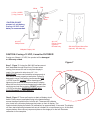
Step 6. Figure 6 shows the different methods of
connecting wires at roof level. Method will depend on
model. Wire colors MUST MATCH, i.e. red to red.
Figure 5
Figure 6
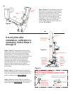
Step 3. Figure 4. To install Sensor with your
RM model, remove dish from backup frame.
Place Sensor inside backup frame, Figure 4.
Cable must exit from bottom of Sensor.
Route under pins, refer to Figure 4. Be sure
case is placed so mounting screws are
completely in slots. Fasten Sensor case to
frame, being careful not to overtighten
screws. Secure Sensor cable to coax with
wire ties. Go to Step 9.
Backup
Frame
Sensor
Case
Sensor
Cable
Pliers not supplied
3M UR Terminal
Slide wires all
the way in.
DO NOT strip
wires, terminal
is self stripping.
Squeeze pliers until red plunger
is flush with rest of terminal.
Supplied with the DE-4646 only.
NOTE: This terminal is weatherproof and can be left outside
on the roof as LONG AS IT IS SECURED PROPERLY to prevent
whipping in the wind.
Figure 4
If at any time after
installation, calibration is
necessary, follow Steps 4
through 8.
Adjust
sensor/
mounting
plate until
parallel with
elevating
tube
(Step 2)
Use a level to
ensure antenna
is plumb (90
o
)
Antenna
Use cable
ties provided
to secure
sensor cable
to coax
downlead.
Elevating Tube


