


21
Before beginning the installation of your
Freedom Marine Inverter/Charger, read the
owner’s manual. Disconnect all sources of
AC and DC power to prevent accidental
shock. Disable and secure all AC and DC
automatic starting and disconnect devices.
CAUTION This equipment is not ignition
INSTALLATION PRECAUTIONS
protected and employs components that
can produce arcs or sparks. To reduce the
risk of fire or explosions, do not install
in unvented compartments containing
batteries or flammable gasses or areas
in which ignition-protected equipment is
required.
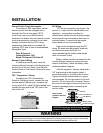
CAUTION To reduce the risk of electric shock
and prevent premature failure due to corrosion,
do not mount where exposed to rain,
dripping or spray.
CAUTION To reduce the risk of fire, do not
obstruct ventilation openings. Do not mount
in a zero clearance compartment—
overheating may result.
CAUTION Risk of electrical shock. Both
AC and DC voltage sources are
terminated inside this equipment. Before
servicing disconnect all inputs and outputs.
Typical Tools Needed
Flathead and Phillips Screwdrivers
Wrench for connecting battery cables (9/16'')
Wire Cutters
Wire Strippers
Misc. assorted wire ties and connectors
Accessories Needed for Installation
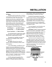
Before beginning installation, unpack the
inverter/charger, record the serial number on
the warranty card. Retain packing materials for
future use.
Confirm that your shipping carton contains:
• Inverter/Charger
• TSC temperature sensor with 20' cable
• Owner's Manual
• Warranty Card
• DC Battery Cable Covers & Screws (4)
• AC Access Cover plate & Screws (2)
• Compression Terminal Block
(2) Freedom 10, 15, 20
(4) Freedom 25 & 30
If any components are missing, contact
Customer Service: 1 800 670 0707.
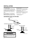
WARNING
For continued protection against risk of
electric shock, use only the ground-fault
circuit interrupter (GFCI) type receptacles
detailed in this manual. Other types may
fail to operate properly when connected to
this inverter, resulting in a potential shock
hazard.
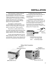
• Fuse: UL Listed DC Rated slow blow fuse
as required by NEC
• Electrical wire (10 gauge) for AC input
wiring. Consult NEC for proper size for
output wiring.
• Battery Cables with 3/8'' ring terminal
1 positive, 1 negative (Consult NEC for
proper size)
• DC fuse cable
• Mounting Bolts (4)
• Strain Relief (2)