


30
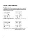
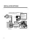
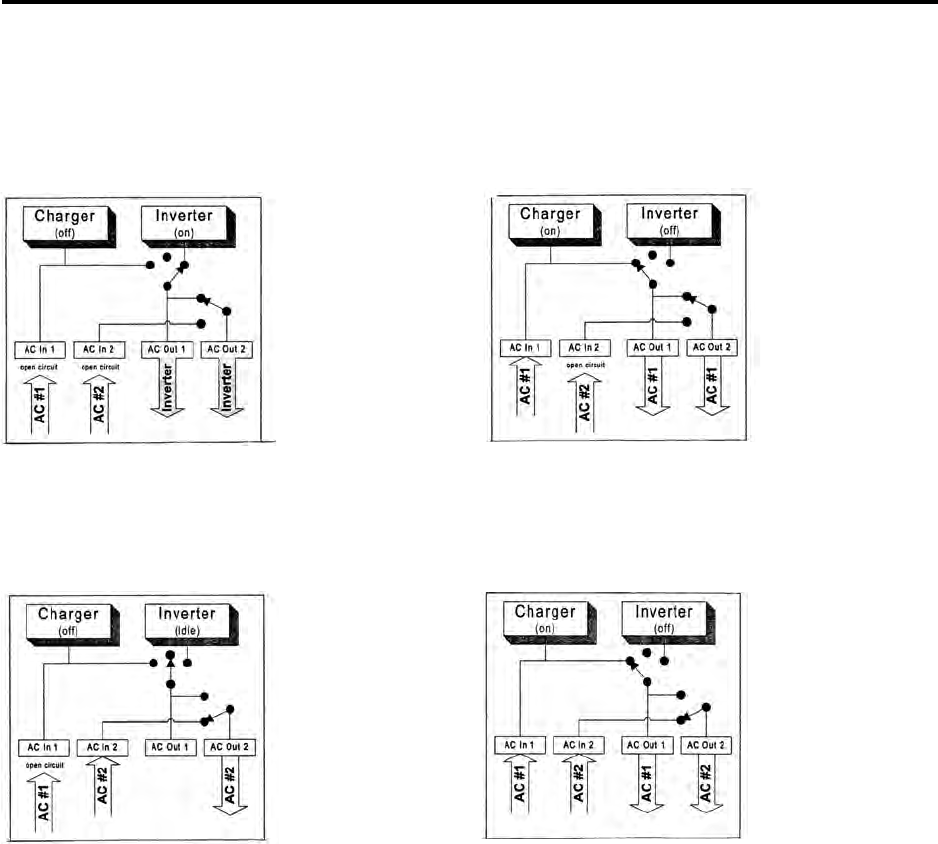
Dual In/Dual Out Configuration
These diagrams are intended to be a visual representation of the AC power “path” through the
Inverter/Charger with AC power applied to 1, 2, or both of the AC input connections. These dia-
grams are meant only to show switching characteristics, and they are not intended to illustrate
actual circuit components or connections.
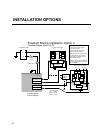
Inverter Mode: With no power applied to either AC input,
the Inverter is On and power is applied to both the “AC
Out 1” and “AC Out 2” outputs.
Charger/Transfer Mode 1: With power applied to “AC In
1” only, the Charger is on and power from “AC In 1” is
transferred to both AC outputs. Power to both outputs is
“shared” with the Charger.
Transfer Mode: With power applied to “AC In 2” only, the
Charger is Off and power from “AC In 2” is transferred to
“AC Out 2” only. “AC Out 1” is not active.
Charger/Transfer Mode 2: With power applied to both
AC inputs, the Charger is On, power from “AC In 1” is
transferred to “AC Out 1” and power from “AC In 2” is
transferred to “AC Out 2.” Only “AC In 1” power is
“shared” with the charger.
INSTALLATION OPTIONS