


32
INSTALLATION OPTIONS
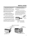
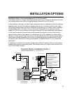
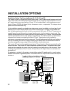
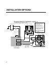
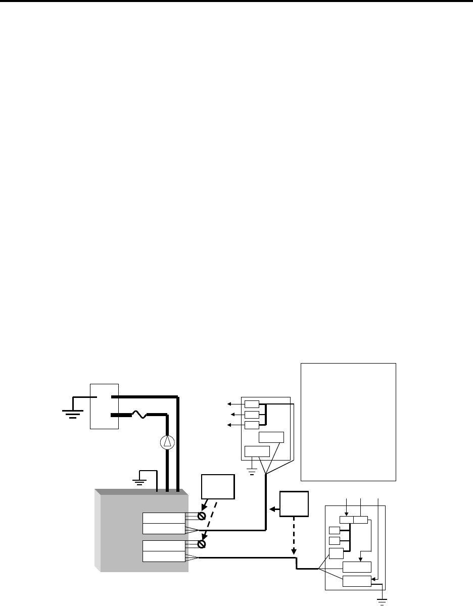
Installation Option 2 for Freedom Marine 10, 15, 20, 25, and 30
The inverter is used in a Single Input/Single Output mode. The AC loads are split between main loads
and inverter loads. The external sources of AC power can be a single 30 amp shorepower source or
a 30 amp breaker from a panel fed by a 50 amp 120 volt single phase (3 wire) shorepower source, 1
leg of a 50 amp 120/240 split phase (4 wire) shorepower source, or a generator. The charger shares
power with the inverter loads only.
In this installation example, one single phase shorepower source is available or only one leg of a split
phase source is used to supply the AC input of the inverter/charger. It is highly recommended that
only the lighter appliances and outlet circuits be connected to the Inverter AC Panel. These loads are
supplied power through the inverter in charge/ transfer mode, or by the inverter in invert mode. The
charger shares power with the inverter loads only and can transfer up to 30 amps. The heavier loads
such as space heaters, stoves, water heaters, air conditioners, AC to DC converters, or other battery
chargers should remain connected to the Main AC Panel. These loads are only supplied by
shorepower or generator power from the main panel. This split load approach will help avoid problems
such as overloading the inverter or rapidly discharging the battery bank, and eliminates the need to
manually manage the energy usage of these loads when using inverter power.
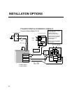
The inverter AC input must be supplied power from a 30 amp breaker in the main panel and from the
main neutral bus. The inverter’s AC output supplies a separate sub panel. The appliance and outlet
loads are then supplied with power from the inverter hot and neutral bus in the sub panel. When
installing a Freedom Marine 25 or 30 model, AC Input #2 and AC Output #2 are not used and must
be capped off.
If a generator is installed in the system, a break-before-make AC transfer switch is used to select
between shorepower or generator power. The transfer switch AC output is then routed to the input of
the Main AC Panel.
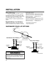
AC Output 2
AC Output 1
AC Input 2
AC Input 1
Ground Bus
Neutral Bus
Cap* Off
each wire
separately
Inverter AC
Sub Panel
To
Inverter
AC
Loads
Class T
Fuse
Freedom Marine Installation Option 2
Freedom Marine Model 10, 15, 20, 25, 30
Single Input/ Single Output
30 Amp Transfer Switch Power
Shares with Charger.
AC ground and DC ground are
shown connected, therefore,
galvanic protection is
recommended
*AC Input 2 and AC Output 2 are
available only on Freedom 25
and 30 Models.
** Always consult Local and
National Electrical Codes for
proper wire size prior to
installation.
Freedom Marine
Inverter/Charger
10/3
AWG
Wire**
-
+
+
-
Hot
Bus
Ground Bus
From Shore or Generator
Hot Neu. Gnd.
Main AC
Panel
Neutral Bus
30
Hot
Bus
AC Wire Colors
Hot = Black
Neutral
=White
Ground
=
Green
12 VDC Battery Bank
Battery Switch
Main
Main