


35
INSTALLATION OPTIONS
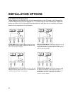
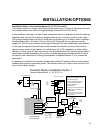
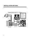
Installation Option 4 for Freedom Marine 25 and 30
The inverter is used in a Dual Input/Dual Output mode. The AC loads are split between main
loads and inverter loads. The external sources of AC power can be two different 30 amp
shorepower sources (both neutrals and both “Hots” must be kept separate), or two 30 amp
breakers from a panel fed by a 50 amp 120 volt single phase (3 wire) shorepower source, a 50
amp 120/240 volt split phase (4 wire) shorepower source, or a generator. The charger uses one
30 amp source of power (AC Input #1) and the other 30 amp source (AC Input #2) transfers
through the inverter to the inverter loads connected to AC Output #2. In inverter mode, the inverter
powers both groups of inverter loads. In charge/transfer mode, up to 60 amps can be transferred
to the inverter loads. The inverter loads are split into two groups so that these loads can be used
to help balance the two legs of shorepower or generator power.
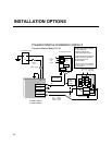
It is highly recommended that only the lighter appliances and outlet circuits be connected to the
Inverter AC Panel. These loads are supplied power through the inverter in charge/transfer mode,
or by the inverter in invert mode. The heavier loads such as space heaters, stoves, water heaters,
air conditioners, AC to DC converters, or other battery chargers should remain connected to the
Main AC Panel. These loads are only supplied by shorepower or generator power from the main
panel. This split load approach will help avoid problems such as overloading the inverter or
rapidly discharging the battery bank, and eliminates the need to manually manage the energy
usage of these loads when using inverter power.
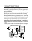
The inverter AC Input #1 must be supplied power from a 30 amp breaker and neutral in the main
panel and is used to power the charger and transfer up to 30 amps through to the inverter loads
connected to AC Output #1. AC Input #2 must be supplied by a second 30 amp breaker in the
main panel which transfers through the inverter to AC Output #2. These two input breakers can
be supplied by the same phase or by opposite phases. The inverter AC outputs supply a separate
sub panel. The appliance and outlet loads are then supplied with power from the inverter hot and
inverter neutral buses in the sub panel.
If a generator is installed in the system, a break-before-make AC transfer switch is used to
select between shorepower or generator power. The transfer switch AC output is then routed to
the input of the Main AC Panel.
If only AC Input #1 is supplied power, the unit will charge and transfer up to 30 amps through to
both groups of inverter loads. The charger will power share with both groups of inverter loads.
If only AC Input #2 is supplied power, the unit will not charge, and will only transfer 30 amps
through to the inverter loads connected to AC Output #2 only.