


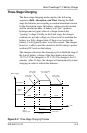
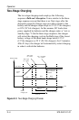
Introduction
1–16 975-0401-01-01
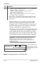
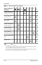
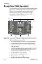
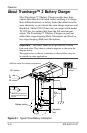
4 Battery Status LEDs
Displays the present status of each battery (or each battery bank). This
feature is available only on the Remote Panel.
Each row represents the battery (or battery bank) number
designation—1, 2, or 3. Each column represents Low, Medium, or
Full battery capacity.
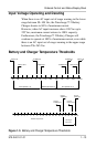
NOTE: These levels are measured when the battery is not under
charge during the 15-minute charge interruption intervals.
The thresholds are:
• Low if battery voltage is below 11.9 V (23.8 V for 24 Vdc
systems)
• Medium if the voltage is 11.9 to 12.4 V (23.8 to 24.8 V for
24 Vdc systems)
• Full if the voltage is above 12.4 V (24.8 V for 24 Vdc systems)
5 Status Button
• Press and hold to enter or exit Setup Mode.
• When in Setup Mode: Press to select the Battery Temperature:
C
old, Warm, or Hot.
• When setting or cancelling an Equalization program: Press and
hold both the Status and
ON/STANDBY buttons.
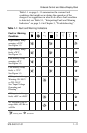
6 Fault/Warning LED
The LED displays a solid light to indicate a fault condition or flashes
intermittently in combination with a flashing Charging Output (%)
LED to display a warning condition (6a). See Table 1-1, “Fault and
Warning Indicators” on page 1–11 for details.
7 Max. Output (%) LED
The LED illuminates a solid light corresponding to the Maximum
Charger Output % setting.
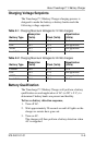
Item Description