n E
ri
Win
4 -
GB
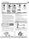
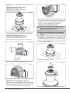
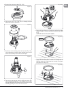
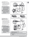
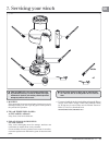
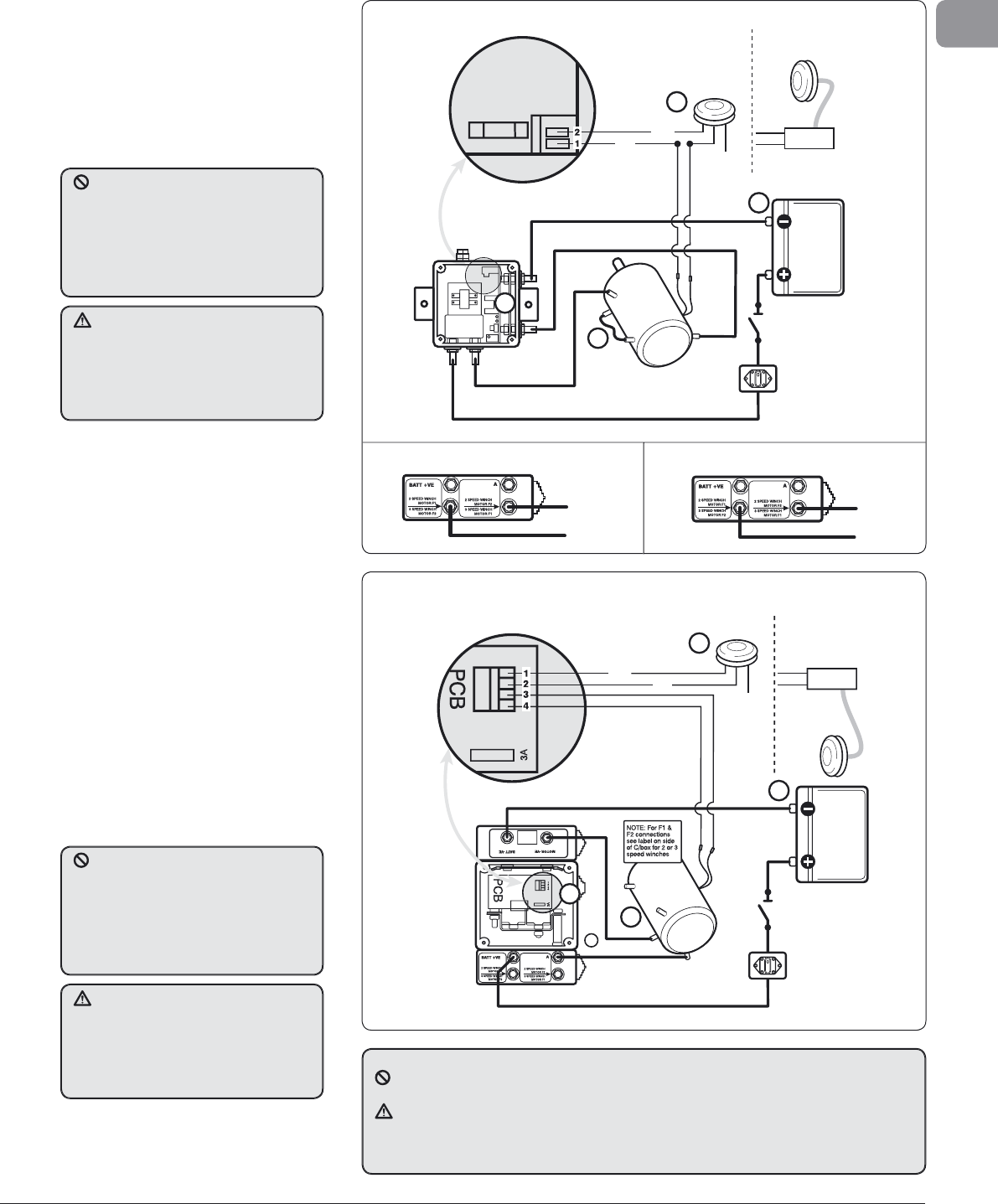
.3 ELS Electric Load
ensin
50-65, 12 V or 24 V
• This installation controls the winch b
ewmar’s uni
ue Overload Protection
ontrol Box (Fi
3.3.1), this allows the
inch to be o
erated u
to the Safe
orkin
Load for winch size.
• Ot
er features as Section 3.1
PCB
Thermal
Cutout
Isolator/Safety
Switch
Circuit
Breaker
Battery
A2
F1
Control Box
Battery +VE
Motor +VE
Grey
Not Used
Electric Switch Kit
69000016
1
Battery –VE
Motor –VE
A1
F2
2
4
Air Deck
Switch Kit
69000022
Sub Box
Black
Blue
3 A
Fuse
Two-way
Terminal Block
3
i
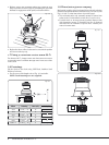
. 3.3.1 12 V or 24 V Control box with overload
rotection. Also see Section 3.7.
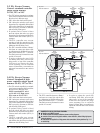
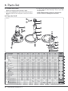
4 EL
Electric Loa
ensing 2/3 speed controlle
/
-77
V or
4
• This installation controls the winch b
ewmar’s uni
ue Overload Protection
Autoshift Control Box (Fi
. 3.4.1).
hi
ll
w
h
win
h
r
in
st an
if reac
es t
e Safe Wor
ing
oa
, for t
e winc
size an
gear, wi
utomatica
y s
ift t
e winc
into 2n
ear for comp
ete
oa
contro
.
In t
e case of a 3 spee
winc
Fig.
.4.1
t
e switc
must
e re-se
ecte
o achieve 3rd
ear.
ig. 3.4.1a 2
peed winch electrical connection
Blue
Black
Grey
Not Used
Electric Switch Kit
69000016
2
Air Deck
Switch Kit
69000022
Sub Box
Isolator/Safety
Switch
Circuit
Breaker
Battery
F1
Control Box
Battery +VE
Motor – VE
1
Battery –VE
Motor –VE
A2
A1
F2
3
4
Thermal
Cutout
8
i
. 3.4.1 2/3 S
eed 12 V or 24 V control box with overload
rotection. Also see Section 3.7
i
. 3.4.1b 3 S
eed winch electrical connections
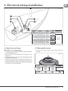
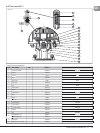
onnect the power supply cables
to the batter
last when the winch
nstallation has been com
leted
n
h
k
f
r
rr
t in
t
ll
ti
n.
In
rr
t
nn
ti
n
f m
t
r
l
ay dama
e the unit
Total volta
e dro
MUST NOT exceed
% of su
ly over com
leted cablin
nstallation.
heck all connections
or water tight security. Lewmar
ecommends an isolator to be
tted in
t
e c
rcu
t
n an access
e pos
t
on as
close as
ossible to the su
ly
onnect the power supply cables
to t
e
attery
ast w
en t
e w
nc
nstallation has been com
leted
n
h
k
f
r
rr
t in
t
ll
ti
n.
In
rr
t
nn
ti
n
f m
t
r
l
ay dama
e the unit
Total volta
e dro
MUST NOT exceed
% of su
ly over com
leted cablin
nstallation.
heck all connections
or water tight security. Lewmar
ecommends an isolator to be
tted in
t
e c
rcu
t
n an access
e pos
t
on as
c
ose as poss
e to t
e supp
y
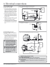
N
MBER KEY F
R ALL ELE
TRI
AL DIA
RAM
Ne
ative earth MUST be used
The deck switch wires MU
T be fi tted as shown on wiring diagrams
onnect all low power wiring
deck switches, motor cutout etc.
before fi tting high power
ca
es to contro
er
able boots are supplied for all high power cable connections, follow guidelines Fig. 2.1.1
or cable sizin
F1
F2
F2
F1