1
cean Electric Winches 34 - 7
. Electrical connection
3 Amp
Slow Blow Fuse
Customer Supplied
Thermal
Cutout
Isolator/Safety
Switch
Circuit
Breaker
Battery
D2
D1
Contactor
12 V - 18000301
24 V - 18000302
Battery +VE
Motor +VE
Grey
Not Used
Electric Switch Kit
69000018
Blue
Black
Battery – VE
A2
2
3
1
4
Fi
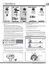
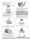
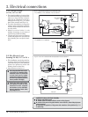
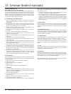
. 3.1.1 Sin
le direction contactor in box with thermal cutout
2 V (18000301) or 24 V (18000302). Also see
ection 3.7
3.1 E
erie
Electric
4-4
,
V or
4 V
• T
is simp
e insta
ation of a power
rive
unit, motor an
switc
gear contro
s t
e
winc
y a sing
e
irection contactor,
w
ic
can
e a Contactor
ouse
in a
water
roof box (Fi
3.1.1), or a stand
alone N
lon encased unit (Fig 3.1.2).
• The motor thermal tri
is connected to
monitor motor tem
erature while the
Lewmar safet
electric deck switch can
e easi
y wire
.
• Manua
overri
e faci
ity is sti
avai
a
e for
ac
up, or as a means of
experiencing tra
itiona
sai
ing.
• Two p
us one spee
comes as stan
ar
contro
w
ic
gives two spee
manua
drive (handle)
lus one s
eed electric
riv
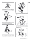
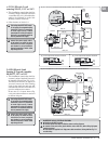
Fig. 3.1.2
ontactor
2 V
0052505
or 24 V
0052506
D1
PCB
D2
A2
Thermal
Cutout
Isolator/Safety
Switch
Circuit
Breaker
Battery
Control Box
Battery +VE
Motor + VE
Grey
Not Used
Electric Switch Kit
69000016
1
Battery –VE
Motor –VE
2
4
Air Deck
Switch Kit
69000022
Sub Box
Black
Blue
3 A
Fuse
Two-way
Terminal Block
3
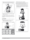
ig. 3.2.1 12 V or 24 V
ontrol box with overload protection. Also see
ection 3.7.
3
2 EL
Electric Loa
Sensing 34-48, 12 V or 24
• This installation controls the winch b
Lewmar’s uni
ue Overload Protection
Contro
Box
Fig 3.2.1
, t
is a
ows t
e
winc
to
e operate
up to t
e Safe
Wor
ing Loa
for winc
size.
• Ot
er features as Section 3.1
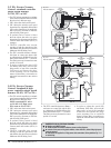
Connect the
ower su
ly cables
o the batter
last when the winch
installation has been com
leted
and checked
or correct installation.
Incorrect connection o
motor cables
may
amage t
e un
t
Total voltage drop MU
T N
T exceed
of supply over completed cabling
installation.
heck all connections
or water tight security. Lewmar
r
mm
n
n i
l
t
r t
fi tt
in
he circuit in an accessible
osition as
lose as
ossible to the su
ly
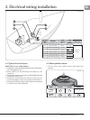
MBER KEY F
R ALL ELE
TRI
AL DIA
RAM
Ne
ative earth MUST be used
The deck switch wires MU
T be fi tted as shown on wiring diagrams
onnect all low power wiring
deck switches, motor cutout etc.
before fi tting high power
a
es to contro
er.
able boots are supplied for all high power cable connections, follow guidelines Fig. 2.1.1
for cable sizin
.
Battery +VE
Motor +VE
Electric
Switch Kit
69000018
3 Amp
Slow Blow Fuse
Customer Supplied
Grey
Not Used
Blue
Black
Thermal
Cutout
0 V/Motor A2