TROUBLESHOOTING & REPAIR
F-12 F-12
POWER WAVE 455M/MSTT
Return to Section TOC Return to Section TOC Return to Section TOC Return to Section TOC
Return to Master TOC Return to Master TOC Return to Master TOC Return to Master TOC
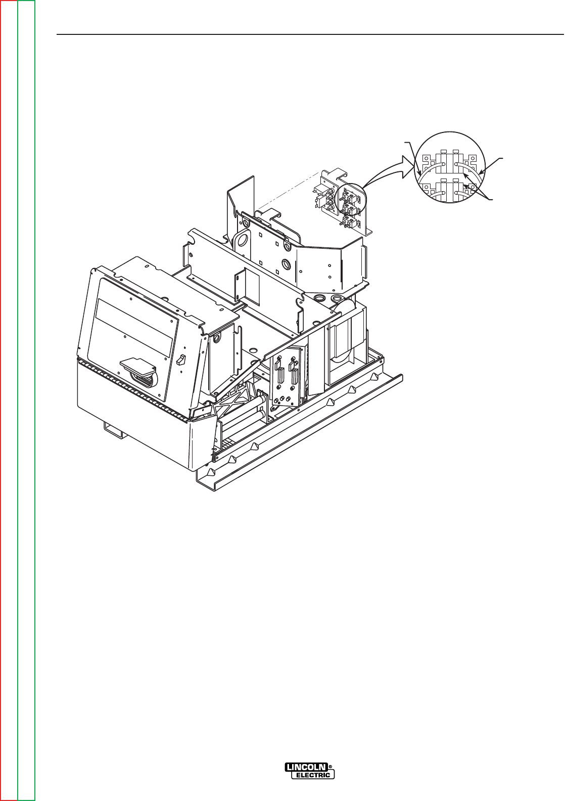
FIGURE F.2 – RECONNECT SWITCHES
SWITCH BOARD TEST (CONTINUED)
TEST PROCEDURE
1. Remove input power to the Power Wave
455M.
2. Perform the Capacitor Discha rge
Procedure.
3. Locate label and remove leads 19C and 19D
from the reconnect switches with the 3/8”
wrench. Note lead placement for reassem-
bly. Clear leads. Refer to Figure F.2.
4. Using the Analog ohmmeter, perform the following
resistance tests. Refer to Figure F.3 for the test
points. Any readings below 100 ohms can be con-
sidered a short circuit. However, readings usually
are below 30 ohms.
Check 11/12 to -20 and 11/12 to +19
Check 13/14 to -20 and +19 to 13/14
5. If any test fails isolate the PC board and
retest, if board still fails, replace switch
board. See Switch Board Removal and
Replacement.
6. If the switch board tests are OK, check the
molex pin connections and associated wiring
from the switch boards to the control board.
See the Wiring Diagram.


