10
SM-97
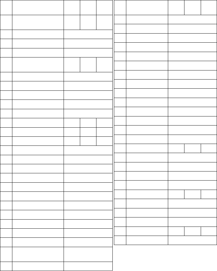
PARTS LIST
Key Description 3A-
1000
3A-
750
3A-
450
Torque Control Ass’y 38641
-1000
38641
-0750
38641
-0450
1 Retainer (2) 24317
2 Spirolox Ring 34262
3 Front Bearing 28069
4 Control Housing Ass’y 40024
-1000
40024
-0750
40024
-0450
5 Main Spring 24307
6 Main Spring Anchor 24318
7 Button Head Screw (2) 24319
8 Lock Washer (2) 28106
9 Main Spring Pin 24313
10 Internal Gear 38658 38657 38658
11 Drive Spindle 38664 38664 38661
12 Planet Gear (3) 24504 24364 24321
13 Needle Roller (3 Sets) 24354
14 Roller Retainer (3Sets) 24355
15 Planet Pin (3) 24314
16 Snubber Shim (0-3) 40561
17 O-Ring 28100
18 Quad-Ring 28102
19 O-Ring 28101
20 Quad-Ring 28103
21 Brake Shoe 38643
22 Brake Rolls Retainer 24311
23 Brake Roll (3) 24324
24 Bearing Race Brake-
Cam
38644
25 Front Ball Retainer 28088
Key Description 3A-
1000
3A-
0750
3A-
0450
26 Reaction Member 24907
27 Retainer 28096
28 Latch Spring 24913
29 Latch Return Pawl 24911
30 Return Pawl Spring 24912
31 Latch Pin 24333
32 Roll Pin (2) 25177
33 Roll Pin 24908
34 Latch 24910
35
Latch Release Spring
24331
36 Latch Release Pawl 24323
37
Latch Release Pin (2)
24330
38 Dowel Pin 24298
39 Reverse Pawl Pin 24328
40
Tongued ReversePawl
38665 38665 38665
41
Reverse Pawl Spring
24914
42
Grooved ReversePawl
24909
43 Retainer 28067-0001
44 Set Screw (4) 20480
45 Index Plate 38653 40014 38652
46 Screw (2) 24320
47 Rear Bearing 51194
48 Handle Connector 38651
49 Internal Gear 38654 38653 38655
50 Balls (13) 21941
7
SM-97
DISASSEMBLY
The following instructions should be studied carefully before
attempting disassembly of Model ‘3A’ Torq-Air—Matic. In most
cases, the major difficulty encountered has been caused by im-
proper disassembly and reassembly procedures.
Torque control disassembly procedure
If air motor has been operating properly, do not remove it from
torque control section at this time, but proceed as outlined. The
steps to be followed have been grouped. Steps within a group may
be performed in any sequence. The groups, however, cannot and
must not be per-formed out of sequence. All steps within a group
must be completed before proceeding to the following group. Refer
to assembly drawing on Page 11.
Group no.1
(A) Unscrew and remove both spring anchor button head screws. Use
3/16” hexagon key supplied.
(B) (B) Unscrew all four torque setting set screws halfway out at
rear of control housing. Use 1/8” hexagon key supplied.
(C) Remove outside bearing shaft retainer ring (Piece No.1).
Group no. 2
(A) Grasp unit by torque control housing with the 1/2” diameter
output spindle uppermost and vertical. Hold it with the motor
handle 1/2’ to 1” above the work surface.
(B) With a soft faced hammer, tap the output spindle gently. The entire internal mech-anism
will fall free as soon as the reduced diameter portion of
output spindle has pass-ed through front ball bearing.
NOTE: Avoid hitting this bearing or housing.
Group no.3
(A) Remove inside bearing shaft retainer ring (Pc #1).
(B) Lift out front ball bearing (Pc #25).
(C) Lift off front brake shoe (Pc #21 ).
(D) Remove 3 brake rolls (Pc #23).
(E) Lift off brake roll retaining ring (Pc #22 ).
Group no.4
(A) The subassembly consisting of reaction member assembly with
latch and various pawls, mainspring with its pin and anchor
and brake cam may then be lifted up off motor drive spindle
assembly.
(B) When failure is due to a malfunction of torque control unit,
the failing parts, usually, can be found easily by observing
operations of the various pawis and latch. This can be done
by holding subassembly in the hand and applying torque or
turning force to internal gear (Pc #10) within reaction mem-
ber (Pc #26). See Trouble Shooting Chart.


