


34-8700-5191-8 2 Revision 10/03/07
DISASSEMBLY INSTRUCTIONS
Changing Grips:
1. The Grip has two “tabs” that wrap around the body of
the sander under the inlet and exhaust. Use a small
screwdriver to pick out one of the “tabs” of the Grip,
and then continue to go underneath the Grip with the
screwdriver and pry the Grip off of sander. To install a
new Grip, hold the Grip by the tabs making them face
outward, align the Grip and slide it under the Throttle
Lever then press the Grip down until it seats onto the
top of the sander. Make sure the two “tabs” seat under
the inlet and exhaust.
Motor Disassembly:
1. Lightly secure the tool in a vise using the T-7 Soft Collar
or padded jaw vice and remove the pad with the 24 mm
Pad Wrench then remove the Shroud or Skirt (which-
ever applies).
2. Remove the Lock Ring with the T-6 Motor Lock Ring
Wrench/Spindle Puller Tool. The motor assembly can
now be lifted out of the Housing.
3. Secure the motor assembly by clamping the 5 in. or 6
in. (125 or 150 mm) Shaft Balancer in a padded jaw vise
and remove the Retaining Ring and the O-Ring from the
Cylinder.
4. Remove the Rear Endplate. This may require support-
ing the Rear Endplate with a Bearing Separator and
lightly pressing the shaft through the Bearing and Rear
Endplate. Remove Cylinder and the Vanes and Rotor
Set from the shaft of the Shaft Balancer. Remove the
Key then press off the Front Endplate (with Bearing), O-
Ring and the Lock Ring. It may be necessary to remove
the Bearing with a Bearing Separator if it came out of
the Front Endplate and stuck to the shaft of the Shaft
Balancer.
5. Remove the Bearing(s) from the Endplates by using the
T-8 Bearing Removal Tool to press out the Bearings.
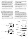
Shaft Balancer and Spindle Disassembly:
1. Grip the shaft end of the Shaft Balancer in a padded
vise. With a thin screwdriver pick out the slotted end of
the Retaining Ring and peel out.
2. Screw the threaded end of the T-6 Motor Lock Ring
Wrench/Spindle Puller Tool into the Spindle until hand
tight. Apply a gentle heat from a propane torch or hot
air gun to the large end of the Balancer Shaft until it is
about 212° F (100° C) to soften the adhesive. Do not
over heat. Remove the Spindle assembly by using the
slider to give sharp outward blows to the Spindle. Allow
the parts to cool so they are safe to handle. Follow one
of the appropriate directions below:
• If the Bearing come out with the spindle, use a small
Bearing Separator to remove it. Move onto step 3.
• If the Bearing stays in the Shaft Balancer. Follow
steps A - D below.
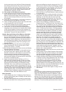
Procedure for removal of the Bearings from the Shaft
Balancer:
A. Position the Set Screw in the top of the T-9 12 mm ID
Bearing Puller.
B. Make sure the Retaining Ring is removed, then press
the Bearing Puller into the I.D. of Bearing until the Bear-
ing Puller hits the bottom of the Shaft Balancer.
C. Thread the Set Screw down until it hits the bottom of the
Shaft Balancer or becomes very tight. Grip the shaft end
of the Shaft Balancer in a padded vise.
D. Screw the threaded end of the T-6 Motor Lock Ring
Wrench/Spindle Puller Tool into the Bearing Puller until
hand tight. Apply a gentle heat from a propane torch
or hot air gun to the large end of the Shaft Balancer to
re-heat it until it is about 212° F (100° C) to soften the
adhesive. Do not over heat. Remove the Bearing by
using the slider to give sharp outward blows to the Bear-
ing Puller. Allow the Bearing Puller, Bearing and Shaft
Balancer to cool. After cooling, unthread the T-6 Motor
Lock Ring Wrench/Spindle Puller Tool from the Bearing
Puller. Back off the set screw. Secure the Bearing Puller
and Bearings in a Bearing Separator and press out the
Bearing Puller.
3. The beraing shield components are held in place by the
light press t of the Retainer. These components can be
damaged during removal and may need to be replaced
if removed. To remove the Retainer, use an O-ring
pick or a #8 sheet metal screw to grip and pull out the
Retainer. Remove the Valve and Filter from the bore in
the Shaft Balancer. If the Retainer and Valve were not
damaged, they can be reused. However, the lter should
be replaced on re-assembly.
Housing Disassembly:
1. For Non-Vacuum (NV) and Central Vacuum (CV)
machines follow the steps outlined in Section I below.
For Self Generated Vacuum (SGV) machines follow the
steps outlined in Section III.
I. This section is for NV and CV machines.
A) Unscrew the Mufer Housing from the Housing.
B) Remove the Bronze Mufer from the Mufer Housing
and remove the Mufer insert from the cavity of the Muf-
er Housing.
C) For NV machines move onto D. For CV machines move
onto Section II.
D) Remove the NV Shroud. Move onto Step 2.
II. This section continued from Section I for CV Exhaust
machines:
A) Remove the Screw, Washer and Nut.
B) Remove the Ø 1 in. (28 mm) CV Swivel Exhaust As-
sembly or the Ø 3/4 in. (19 mm) CV Swivel Exhaust
Assembly from the Shroud or Clean Sanding Shroud.
C) Remove the Shroud or Clean Sanding Shroud from the
Housing. Move onto step 2.
III. This section is for SGV Exhaust machines:
A) Unscrew the SGV Retainer with an 8 mm hex wrench.
NOTICE: To receive any expressed or implied warranty, the tool must be repaired by an authorized Service Center.
The 5 in (127 mm.) and 6 in. (150 mm) Random Orbital Sander Service Instructions section provided is for use after completion of
the warranty period.
12,000 RPM – 5 in. (127 mm) and 6 in. (150 mm)
RANDOM ORBITAL SANDERS SERVICE INSTRUCTIONS