


34-8700-5191-8 3 Revision 10/03/07
B) Remove the Ø 1 in. (28 mm) Hose SGV Swivel Exhaust
Assembly from the Housing and SGV Skirt Adapter or
SGV Shroud Adapter.
C) Pull the SGV Retainer out of the bore of the Swivel
Exhaust Assembly and remove the two O-rings.
D) Remove the Vacuum Shroud or Vacuum Skirt from the
Housing. Move onto step 2.
2. Place the Speed Control to the midway position and
remove the Retaining Ring. NOTE: If the machine is a
vacuum model, the vacuum exhaust must be removed
(see Section 1 above for removal) before the Retaining
Ring can be removed with lock ring pliers. The Speed
Control will now pull straight out. Remove the O-ring.
3. Unscrew the Inlet Bushing Assembly from the Housing.
Remove the Valve Spring, Valve, Valve Seat, Valve
Stem and O-Ring.
4. Press out the Spring Pin from the Housing and remove
the Throttle Lever.
ASSEMBLY INSTRUCTIONS
NOTE: All assembly must be done with clean dry parts and
all bearings are to be pressed in place by the correct tools
and procedures as outlined by the bearing manufacturers.
Housing Assembly:
1. Install Throttle Lever into Housing with the Spring Pin.
2. Lightly grease the O-ring and place it on the Speed
Control. Install Valve Stem, O-ring (cleaned and lightly
greased) and insert the Speed control into the Hous-
ing in the midway position. Install the Retaining Ring.
CAUTION: Make sure the Retaining Ring is completely
snapped into groove in the Housing.
3. Install the Valve Seat, the Valve and the Valve Spring.
Coat the threads of the Bushing Assembly with 1 or 2
drops of 3M Rite-Loc TL22 or equivalent non-permanent
pipe thread sealant. Screw the assembly into the Hous-
ing. Torque to 60 in/lbs (6.77 Nm.)
4. For NV and CV machines follow the steps outlined in
Section I below. For SGV machines follow the steps in
Section III.
I. This section is for CV and NV
A) Place a clean felt Mufer all-the-way into the chamber of
the Mufer Housing. Press the Bronze Mufer onto the
Mufer Housing.
B) Screw the Mufer Housing assembly into the Housing
until hand tight. Use a 21 mm socket/torque wrench
combination to torque the Mufer Housing. Torque to 20
in/lbs (2.25 Nm). For NV machines move onto C. For CV
machines move onto Section II.
C) Install the Non-Vacuum Shroud onto the Housing by
working the shroud over and around the bottom of the
housing anges. Make sure the line up slots (on the
Housing) and tabs (on the Shroud) are engaged. Move
onto the ”Spindle, bearing shield and Shaft Balancer
Assembly” Section.
II. This section continued from Section I for CV Ex-
haust machines:
A) For 5 and 6 in. (125 and 150 mm) machines:
(1) Install the 5 or 6 in. (125 or 150 mm. ) Shroud or 6 in.
(150 mm) Clean Sanding Shroud onto the Housing by
working the shroud over and around the bottom of the
housing anges. Slide the inlet end of the Ø 1 in. (28
mm) CV Swivel Exhaust Assembly or the Ø 3/4 in. (19
mm) CV Swivel Exhaust Assembly into the exhaust port
of the Shroud or Clean Sanding Shroud until it hits the
stop on the Swivel Exhaust Assembly.
NOTE: For installation of Shrouds and Skirts make sure the
line up slots (on the Housing) and tabs (on the Shroud or
Skirt) are engaged. Make sure that the key on the Swivel
Exhaust Assembly bracket is aligned and engaged with the
keyway on the Housing.
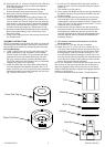
B) Place the Washer over the Screw. Thread the screw
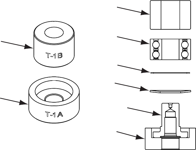
Press Tool Top
Press Tool Base
Shim
Bearing
Washer
Spindle
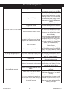
T-1B
T-1A