


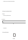
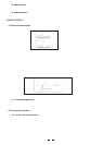
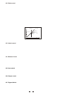

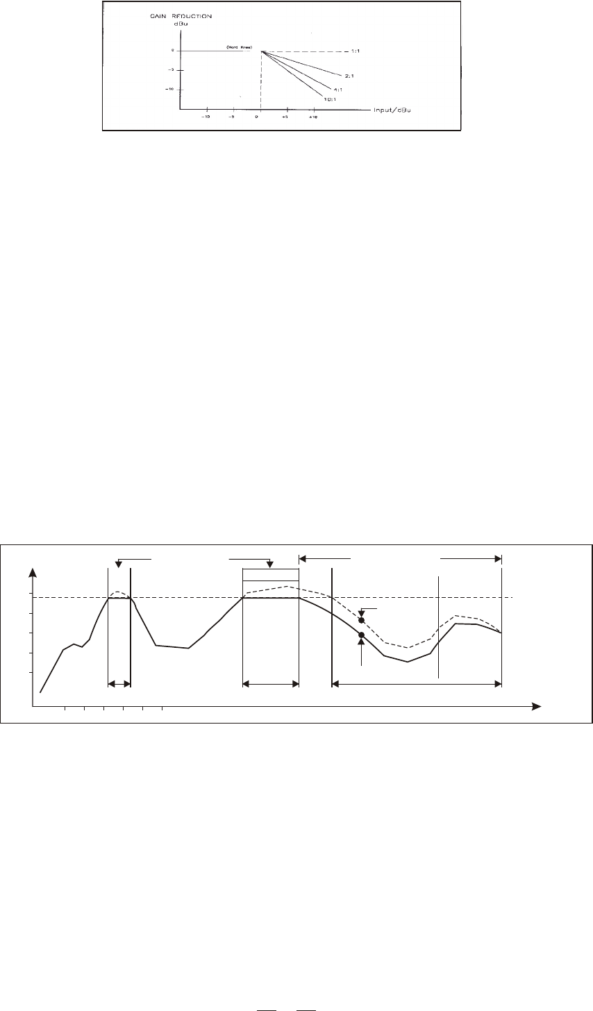
Chart. 7 SGC characteristic of the limiter section
5. INSTALLATION AND CONNECTION
5.1 Mains Connection
ACL2 PRO is provided with dual voltage plug. You must check the power supply Voltage available in your Country
before connecting the power cord in the wall outlet. Please see Page9, paragraph 22 for further info.
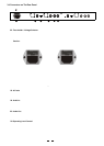
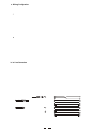
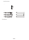
5.2 Audio connection
The ACL2 PRO Compressor/Limiter/Gate is equipped with balanced XLR connectors as well as 1/4" phone jack and
can be connected with other units in different ways to support a vast range of applications without experiencing a
signal loss.
12
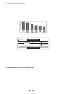
4.2.8 Gain Reduction Meter
This consists of 12 LED on the front of the ACL2 PRO. Through this Led meter you can visualise the amount
of gain reduction at any given time.
Chart. 6 The effect of a compressor can be expressed as the amount
of gain reduction that is taking place for any given input
4.3 Peak Limiter Section
How fast is the compressor to react to a signal which is above the threshold point? This is determined by the attack
time. A longer attack time is advisable to process low frequencies while shorter attack time is preferable for high
frequencies. In this way you will avoid undesired dynamic distortion. But what about if you are mixing a program
with a wide range of frequencies? In this case you should choose a setting that would benefit the low frequency
better.
Well, life is not that easy for conventional compressor/limiters. Ok you handle an audio signal made by a wide
range of frequencies and you have chosen a longer attack time. But, if using your ACL2 PRO as a limiter the
fast high frequencies will pass through untouched because the attack time is too slow and such transients could
cause distortion when the unit is connected to broadcast devices or tape recorders. The solution in ACL2 PRO is
represented by our Smart Gain Control (SGC) limiter circuit. The curve in bold is the output signal and the dashed
curve above it is the input signal. The area in between the two is the amount of gain reduction.
The unit will activate the limiter when the signal exceeds the threshold for more than 15 microseconds. Then 1
second after that the signal is below threshold again, reduction goes back to 0dB and in this case input and output
signals are again identical.
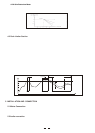
Peak Limiting
6ms 15ms
Level
Program Limiting
Input
Release
Output
approx. 1 s
Threshold
t/ms
30
20
10