


UG-015 Evaluation Board User Guide
Rev. 0 | Page 4 of 12
HARDWARE CONFIGURATION
To configure the hardware, follow these steps:
1. Plug the USB A to Mini-B cable into the PC, if the cable is
not already connected.
2. Connect the ISEB to the USB cable.
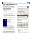
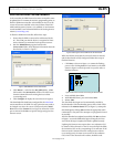
If prompted to install the device, see the Software
Configuration section for details on how to install and
select the correct driver.
3. Connect the ISEB to the ADXL345 satellite using the
18-inch, 20-pin ribbon cable. This cable is keyed to prevent
inserting it backwards and causing damage to the system.
4. Connect the ADXL345 satellite to the opposite end of the
ribbon cable.
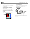
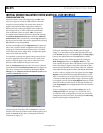
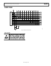
5. Verify that the jumpers located in the center of the
ADXL345 satellite are configured as shown in Figure 5.
CONNECTOR
ADXL345
JUMPER
POSITIONS
08119-005
Figure 5. Correct Jumper Positions for the ADXL345 Satellite
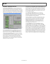
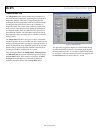
6. Place the ADXL345 ultralow power accelerometer into the
socket on the satellite board.
The Socket Pin 1 Indicator is located inside the socket close
to the hinge, as shown in Figure 6. This pin indicator should
match up with the Pin 1 Indicator on the ADXL345.
7. After positioning the ADXL345 in the socket, firmly close
the socket until it latches.
ADXL345 SOCKET
PIN 1 INDICATOR
ADXL345
ACCELEROMETER
PIN 1 INDICATOR
08119-006
Figure 6. Location of Pin 1 Indicators for the ADXL345 Accelerometer and Socket
The inertial sensor evaluation system should now be set up and
ready to use.