


Evaluation Board User Guide UG-015
Rev. 0 | Page 7 of 12
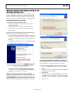
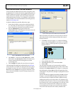
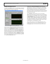
REAL-TIME MEASUREMENT TAB
The Real-Time Measurement tab configures the inertial sensor
evaluation system and the ADXL345 for real-time acceleration
monitoring. The tab contains an oscilloscope-like interface that
you can use to view the output of the accelerometer and adjust
the relevant parameters, such as bandwidth, range, and offset
(see Figure 12).
0
8119-009
Figure 12. Real-Time Measurement Tab
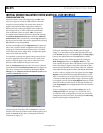
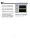
Within the Real-Time Measurement tab, additional tabs exist
for displaying the output in terms of least significant bits (LSBs)
or acceleration in g’s. In the Output – LSB tab, the output range
can be adjusted by using the graph tools in the upper right
corner or by selecting the x-axis (labeled Sample) or y-axis
(labeled Output [LSB]) limits and typing a new value. For
example, selecting 1024 on the y-axis and typing 2048 adjusts
the scale to show +2048 LSBs to −1024 LSBs.
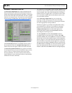
The configuration section is at the bottom of the Real-Time
Measurement tab. In the Data Rate and Resolution box, the
output data rate and g range can be adjusted. Selecting the
Full-Resolution checkbox places the part into full-resolution
mode where the scale factor is fixed. Deselecting this checkbox
places the part into fixed 10-bit mode. For more information
about the operation of the part, refer to the ADXL345 data sheet.
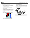
The Self Test button toggles the self-test bit of the ADXL345.
When self-test is activated, the sensor beam is deflected. The
electronics detect this by means of a shift in all three axes. When
self-test is enabled, the indicator next to the Self Test button is
lit. Clicking the Self Test button when self-test is enabled turns
the self-test feature off and causes the Self Test indicator to dim.
Self-test is enabled as long as the indicator is lit.
The ADXL345 provides three offset registers that are used
for calibration and offset adjustment. On the Real-Time
Measurement tab, these registers are easily accessible for
programming offset values. This can be done in the Offset
Adjustment box by typing a value into the text box below the
corresponding axis knob or by clicking and holding the knob
and rotating it on the screen with the mouse cursor. The value
entered is directly written into the offset registers.
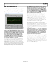
After configuration, you can begin real-time measurement by
clicking the Start Meas button. This causes many of the options
and tabs to be grayed out or to disappear, to prevent software
conflicts, until the Stop Meas button is clicked. The accelerometer
output data then begins to flow across the screen at the selected
output data rate.
Up to the last 8192 samples (x-, y-, and z-axis) of accelerometer
output data can be saved to a .txt file. Each file created contains
a header with the date, bias values, and accelerometer data, in
LSBs, aligned in tab-delimited columns. To save the data, you
must enable the Save Data button. Click this button and type
in or select a file name with a .txt extension.
Each time a measurement is performed, the new data is appended
to the old data. This means that saving data also saves old data,
if new data is less than 8192 samples, unless the old data is first
cleared. The data saved to a file is the LSB data; therefore, the
Output – LSB window must be cleared so that old data is not
saved. To clear the Output – LSB window, right-click the x-axis
(labeled Sample) in the space between Sample and the window
and select the Clear Chart option.