


UG-015 Evaluation Board User Guide
Rev. 0 | Page 8 of 12
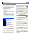
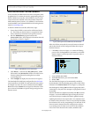
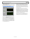
INTERRUPT CONFIGURATION TAB
The Interrupt Configuration tab is used to demonstrate the
built-in functions of the ADXL345. By selecting the functions to
enable and configuring the appropriate parameters, the benefits
and uses of the interrupts can be examined. This tab is updated
whenever an interrupt occurs. This means that some interrupts,
such as inactivity, if enabled alone, will not appear to be updated.
08119-010
Figure 13. Interrupt Configuration Tab
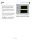
The Current Status indicators are updated when the panel is
first activated and when the Configure Interrupts button is
clicked. They show the register values at the time of the read.
The Interrupt System Parameters box is used to set the built-
in interrupt parameters. Here, the thresholds for tap or activity
events can be set, as well as the many timer values for the
interrupt parameters. The units of each are shown after the
register parameter name, and entered values are automatically
rounded to the nearest valid value.
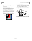
The indicators for ACT_INACT_CTL and TAP _AXIS are used
to select the axes to include in activity, inactivity, and tap events.
For more details, refer to the ADXL345 data sheet. Clicking an
indicator causes it to toggle values. A lit indicator causes a value
of 1 to be written to that bit, and an unlit indicator causes a value
of 0 to be written to that bit.
In the Interrupt Configuration box, you can select the
interrupts to enable. For purposes of the GUI, all enabled
interrupts are mapped to the INT2 pin. Selecting the checkbox
next to the appropriate interrupt enables it.
Note that no registers or parameters are updated after setting
any individual box or indicator. To configure the interrupts
based on new values entered in this box, you must click the
Configure Interrupts button in the bottom right corner.
Clicking this button updates the Current Status indicators
and configures the interrupts as set.
The INT_SOURCE and ACT_TAP_STATUS indicators
are updated when an interrupt occurs. The data ready (DR),
watermark (WM), and overrun (OR) bits are always set because
this tab does not service data-related interrupts. In the configuration
shown in Figure 13, the accelerometer has detected inactivity. If
the accelerometer were moved with enough force to exceed the
504 mg activity threshold, the INACT indicator would dim and
the ACT indicator would light up. If the accelerometer were put
down and undisturbed for the 1 sec inactivity timer, the ACT
indicator would dim and the INACT indicator would again light up.