


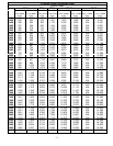
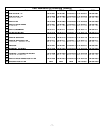
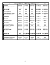

- 12 -
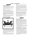
7. Wipe a thin film of Marine Grade Moly Lube onto the
inner race of the large opening in the Drive Plate.
8. Position the Ratchet (6) in the central opening of the
Drive Plate.
9. Insert the Drive Segment (7) into the opening adjacent
to the Ratchet.
Make certain the teeth of the Ratchet
correctly engage the teeth of the Drive Segment.
Reverse the Ratchet if they do not properly engage.
10. Slide the Drive Segment sideways to expose the
spring hole. Install the Segment Spring (14) into the
hole. While compressing the Spring, slide the Drive
Segment inward until the Drive Plate captures the
Segment Spring.
11. Apply a light coat of Marine Grade Moly Lube to
both sides of the Drive Plate and Drive Segment.
Apply some of the Moly Lube to the inner races of
both Side Plate Sleeves (12).
12. While keeping the assembly together, insert the hub
of the Ratchet into the Side Plate Sleeve of the
assembled Side Plate.
13. Place the Left Side Plate Sleeve on the hub of the
Ratchet and align the screw holes for the Spacers.
14. After applying a non-permanent thread-locking
compound to the threads and using hex wrenches,
install the two remaining Lower Spacer Screws.
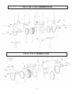
Assembly of the TX-16 and TX-32 Cylinder
Assemblies
1. Grasp the link retaining pin lug in copper-covered,
vise jaws with the Housing (1) horizontal.
2. If the Rod Seal (16) was removed from the Housing,
apply a coat of o-ring lubricant to the Seal and install
it, lip end trailing, in the recess at the bottom of the
piston bore.
3. Press the Slider Pin (14) into one of the Sliders (5)
flush with one side. Install the Pin through the hole in
the piston shaft and press the remaining Slider onto
the Pin.
4. Install the Piston O-ring (17) in the groove of the
piston head.
5. Insert the piston rod, threaded end leading, into the
small central opening from the non-piston end of the
Housing. The notch in the trailing end of the shaft
should be toward the Ball Plunger (13).
6. Insert the piston, hex end trailing, into the bore of the
Housing, and use socket to thread and tighten the
piston onto the piston shaft.
7. Install the End Plug Seal (15) in the groove on the hub
of the End Cap (7).
8. Using the End Plug Wrench (21), thread the
assembled End Cap, o-ring end leading, into the piston
end of the Housing and tighten it.
9. Wrap the threads of the Swivel Sets (18) with Teflon
tape and thread the swivel with the male hose Coupler
(19) into the center of the End Cap. Thread the Swivel
with the female Coupler into the hole in the Housing
directly above the End Cap.
Assembly of the TX-2, TX-4, and TX-8 Cylinder
Assemblies
1. Grasp the link retaining pin lug in copper-covered,
vise jaws with the Housing (1) horizontal.
2. If the Rod Seal (16) was removed from the Housing,
apply a coat of o-ring lubricant to the Seal and install
it, lip end trailing, in the recess at the bottom of the
piston bore.
3. Press the Slider Pin (14) into one of the Sliders (5)
flush with one side. Install the Pin through the hole in
the piston shaft and press the remaining Slider onto
the Pin.
4. Install the Piston O-ring (17) in the grooves of the
piston head.
5. Insert the piston rod, threaded end leading, into the
small central opening from the non-piston end of the
Housing. The notch in the trailing end of the shaft
should be toward the Ball Plunger (13).
6. Insert the piston, hex end trailing, into the bore of the
Housing, and use socket to thread and tighten the
piston onto the piston shaft.
7. Install the End Plug Seal (15) in the groove on the hub
of the End Cap (7).
8. Using the End Plug Wrench (21), thread the
assembled End Cap, o-ring end leading, into the piston
end of the Housing and tighten it.
9. Wrap the threads of the Swivel Sets (18) with Teflon
tape and thread the swivel with the male hose Coupler
(19) into the center of the End Cap. Thread the Swivel
with the female Coupler into the hole in the Housing
directly above the End Cap.
Assembly of the TX-2, TX-4, and TX-8 Cylinder
Assemblies
1. Grasp the link retaining pin lug in copper-covered vise
jaws with the Housing (1) horizontal.
2. If the Rod Seal (16) was removed from the Housing,
apply a coat of o-ring lubricant to the Seal sand install
it, lip end trailing, in the recess at the bottom of the
piston bore.
3. Insert the piston rod, notched end leading, into the
Rod Seal and the small central opening from the
piston end of the Housing. The notch in the leading
end of the shaft should be toward the Ball Plunger
(13).
4. Push the Piston Rod (2) inward until the hole for the
Slider Pin (14) aligns with the holes in the walls of the
Housing.
5. Position one Slider (6) on each side of the piston shaft
and insert the Slider Pin through the hole in the
Housing into both Sliders and the piston shaft. The fit
between the Pin and Sliders is an interference fit. Use
a brass hammer and drift to set the Slider Pin below
NOTICE
In the following step, an excessive amount of
grease will prevent proper tooth engagement
between the Ratchet and the Drive Segment
causing the tool to malfunction.