


- 13 -
the outer edge of both Sliders or deep enough to
prevent the shaft ends from dragging on the Housing
walls.
6. Install the Piston O-ring (17) in the internal groove of
the Seal Ring (5).
7. Install the assembled Seal Ring and Piston O-ring on
the hub at the large end of the Piston Rod.
8. Install the Piston Seal Plate (4) in the inlet end of the
Housing with the side having the countersunk screw
holes trailing.
9. Using a hex wrench and an alternating tightening
procedure, install the Retaining Screws (11). Tighten
each Screw a little at a time to obtain even
compression and expansion of the Piston O-ring and
Seal Ring.
10. Place the Seal Insertion Tool (20) on the inlet end of
the Housing.
11. Install the End Plug Seal (15) in the groove of the
End Cap (7)
12. Insert the assembled End Cap into the Housing
through the Tool with the O-ring end leading and the
threaded inlet hole downward. Push the Cap inward
beyond the Retaining Ring groove and approximately
½” into the Cylinder.
13. Remove the Seal Insertion Tool from the Housing.
14. Install the Retaining Rings (8) in the housing
grooves at the inlet end of the Housing. Install the
Rings with the open ends of both rings at the middle
of the opening and the beveled side of the Rings
toward the End Cap.
15. If an air hose is available, inject some air into the
threaded opening of the End Cap to seat the Retaining
Rings. If air is not available, temporarily thread one of
the Swivel Sets (18) into the threaded opening and
pull the End Cap back against the Retaining Rings to
seat them.
16.
For TX-2 and TX-4 models
position the End
Cover (10) against the Housing and after applying a
non-permanent thread-locking compound to the
threads, install the End Cover Screw (12).
17. Wrap the threads of the Swivel Sets (18) with
Teflon tape and thread the swivel with the male hose
Coupler (19) into the threaded hole in the End Cap.
18. Apply some Marine Grade Moly Lube to the notch
in the Piston Rod and the face of the Sliders.
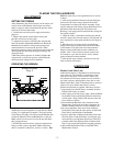
Assembly of the Tool
1. With the Cylinder Assembly in one hand and the
Ratchet Link in the other, hook the notch on the shaft
of the Piston Rod (2) onto the Drive Pin (4) and bring
the two assemblies together.
2. Insert the Link Pin (9) into the hole in the Side Plate (1
or 2) until the Ball Plunger (13) snaps into the annular
groove around the center of the Link Pin.
NOTICE
In the following step, DO NOT use thread-locking
compound on the screw threads.