


P/N 69942 rev. A 3
Banner Engineering Corp. • Minneapolis, MN U.S.A.
www.bannerengineering.com • Tel: 763.544.3164
Installation
Guide
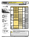
MINI-BEAM
®
ac-Voltage Series
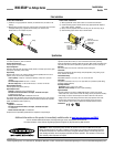
The sensing energy of a convergent-mode
sensor is concentrated at the specified focus
point (see page 1). Convergent-mode sensors are
less sensitive to background reflections, compared with
diffuse-mode sensors. However, if background reflections
are a problem:
• Skew the sensor position at a 10° to 25° angle to eliminate direct
reflections from shiny background surfaces.
• Reduce the reflectivity of the background by painting the surface(s)
flat-black, scuffing any shiny surface, or drilling a large hole, directly
opposite the sensor.
• Reduce the Gain adjustment.
“Flooding” occurs when a portion of
the sensing beam passes around the object to
be sensed. “Burn-through” occurs when a portion
of the emitter’s light energy passes through a thin or
translucent object, and is sensed by the receiver.
To correct either problem, do one or more of the following to
reduce the light energy:
• Reduce the Gain adjustment on the receiver.
• Add an aperture to one or both lenses. (MINI-BEAM apertures, available from
Banner, fit neatly inside the lens assembly.)
• Intentionally misalign the emitter and receiver.
Object
Lo
w
Reflectivity
Backgr
ound
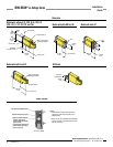
MINI-BEAM sensors perform most reliably if they are properly aligned and securely
mounted. For maximum mechanical stability, final-mount MINI-BEAM sensors
through 18 mm diameter holes by their threaded barrel (where available), or use
a mounting bracket. A complete selection of mounting brackets is available. Visit
www.bannerengineering.com/69942, or contact the factory for information on
mounting options.
Begin with line-of-sight positioning of the MINI-BEAM sensor to its emitter
(opposed-mode sensing) or to its target (all other sensing modes). When using a
retroreflective sensor, the target is the retroreflector (“retro target”). For diffuse or
convergent sensing modes, the target is the object to be detected.
Apply power to the sensor (and to the emitter, if using the opposed mode).
Advance the 15-turn Gain control to maximum (clockwise end of rotation), using
a small flat-blade screwdriver. The Gain control is clutched at both ends to avoid
damage, and will “free-wheel” when either endpoint is reached. See Sensor
Features illustration on page 2.
If the MINI-BEAM sensor is receiving its light signal, the red LED Alignment
indicator will be ON and flashing at a rate proportional to the signal strength
(faster = more signal). Move the sensor (or move the retro target, if applicable)
up-down-right-left (including angular rotation) to find the center of the movement
zone within which the LED indicator remains ON. Reducing the Gain setting will
reduce the size of the movement zone, and enable more precise alignment.
Repeat the alignment motions after each Gain reduction. When optimum
alignment is acheived, mount sensor(s) (and the retro target, if applicable) solidly
in that position. Increase the Gain to maximum.
Test the sensor by placing the object to be detected in the sensing position, then
removing it. The Alignment indicator LED should come ON when the sensing beam
is established (Light condition), and go OFF when the beam is broken (Dark
condition). If the Alignment indicator LED stays ON for both sensing conditions,
consider the following tips for each sensing mode.
If the Alignment LED does not go
OFF when the object is removed
from the beam, the sensor is probably
detecting light reflected from some
background object. To remedy this problem:
• Reduce the reflectivity of the background by painting the
surface(s) flat-black, scuffing any shiny surface, or
drilling a large hole, directly opposite the diffuse sensor.
• Move the sensor closer to the object to be detected and reduce the Gain
adjustment. Rule of thumb for diffuse sensing: The distance to the nearest
background object should be at least three times the sensing distance.
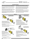
Convergent-Mode Alignment
Light condition: object in beam
Dark condition: no object in beam
Alignment Tips
A highly reflective
object may reflect enough light
back to a retroreflective sensor to allow
that object to slip through the beam,
without being detected. This problem is called
“proxing,” and the following methods may be
used to correct it:
• Position the sensor and retro target so the beam will not
strike a shiny surface perpendicular to the sensor lens.
• Reduce the Gain adjustment.
• Add a polarizing filter (for model SM2A312LV).
Retr
o
Ta
rg
et
Retroreflective-Mode
Alignment
Light condition: no object in beam
Dark condition: object in beam
Object
Opposed-Mode Alignment
Light condition: no object in beam
Dark condition: object in beam
Object
Diffuse-Mode Alignment
Light condition: object in beam
Dark condition: no object in beam
Sensor Mounting and Alignment
Receiver
Emitter