


P/N 69942 rev. A
Banner Engineering Corp., 9714 Tenth Ave. No., Minneapolis, MN 55441 • Phone: 763.544.3164 • www.bannerengineering.com • Email: sensors@bannerengineering.com
Installation
Guide
WARRANTY: Banner Engineering Corp. warrants its products to be free from defects for one year.
Banner Engineering Corp. will repair or replace, free of charge, any product of its manufacture found to
be defective at the time it is returned to the factory during the warranty period. This warranty does not
cover damage or liability for the improper application of Banner products. This warranty is in lieu of any
other warranty either expressed or implied.
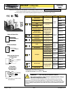
MINI-BEAM
®
ac-Voltage Series
Supply Voltage and Current
24 to 240V ac (50/60 Hz), 250V ac maximum
Supply Protection Circuitry
Protected against transient voltages
Output Configuration
SPST SCR solid-state relay with either normally closed or normally open contact (“light/
dark operate” selectable); 2-wire hookup
Output Rating
Minimum load current 5 mA; maximum steady-state load capability 300 mA to 50°C
ambient (122°F) 100 mA to 70°C ambient (158°F)
Inrush capability: 3 amps for 1 second (non repetitive); 10 amps for 1 cycle (non
repetitive)
OFF-state leakage current: less than 1.7 mA rms
ON-state voltage drop: ≤ 5 volts at 300 mA load, ≤ 10 volts at 15 mA load
Output Protection Circuitry
Protected against false pulse on power-up
Output Response Time
Opposed: 2 millisecond on and 1 millisecond off;
Non-Polarized and Polarized Retro, Convergent, and Plastic Fiber Optic:
4 milliseconds on and off;
Diffuse and Glass Fiber Optic: 8 milliseconds on and off.
OFF response time specification does not include load response of up to 1/2 ac cycle (8.3
milliseconds). Response time specification of load should be considered when important.
(NOTE: 300 millisecond delay on power-up.)
Repeatability
Opposed: 0.3 milliseconds;
Non-Polarized and Polarized Retro, Convergent, and Plastic Fiber Optic:
1.3 milliseconds;
Diffuse and Glass Fiber Optic: 2.6 milliseconds.
Response time and repeatability specifications are independent of signal strength.
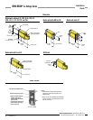
Adjustments
Light/Dark Operate Select switch, and 15-turn slotted brass screw Gain (sensitivity)
adjustment potentiometer (clutched at both ends of travel). Both controls are located on the
rear panel of the sensor and are protected by a gasketed, clear acrylic cover (see page 2).
Indicators
Red indicator LED on rear of sensor is ON when the load is energized.
Construction
Reinforced thermoplastic polyester
housing, totally encapsulated, o-ring sealing, acrylic
lenses, stainless steel screws
Environmental Rating
Meets NEMA standards 1, 2, 3, 3S, 4, 4X, 6, 12, and 13; IEC IP67.
Connections
PVC-jacketed 2-conductor 2 m (6.5') or 9 m (30') cables, or 3-pin Micro-style QD fitting;
QD cables available separately.
Operating Conditions
Temperature: -20° to +70°C (-4° to +158°F)
Maximum relative humidity: 90% at 50°C (non-condensing)
Application Notes
• Overload conditions can destroy ac MINI-BEAM sensors. Directly wiring sensor
without load series, across hot and neutral will damage sensor (except emitter models).
• Low-voltage use requires careful analysis of the load to determine if the sensor’s
leakage current or on-state voltage will interfere with proper operation of the load.
• The false-pulse protection feature may cause momentary drop-out of the load
when the sensor is wired in series or parallel with mechanical switch contacts.
Certifications
Additional information on this product is immediately available online at www.bannerengineering.com/69942
View or download additional information, including excess gain curves, beam patterns and accessories.
For further assistance, contact a Banner Engineering Applications Engineer at (763) 544-3164 or (888) 373-6767.
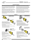
1) With supplied fiber cutter, make a clean cut at control ends of fibers.
2) Unlock the fiber gripper as shown below. Apply appropriate fiber adaptors
prior to fiber insertion, if needed.
3) Gently insert the prepared fiber ends into the ports, as far as they will go.
4) Slide the fiber gripper back to lock, as shown below.
Glass Fiber Installation
Plastic Fiber Installation
Fiber Installation
1) Install the O-ring (supplied with the fiber) on each fiber end, as shown in the
drawing.
2) While pressing the fiber ends firmly into the ports on the sensor front, slide the
U-shaped retaining clip (supplied with the sensor) into the slot in the
sensor’s barrel, until it snaps into place.
Specifications
Trimmed fiber
control ends
Plastic fiber
emitter port
Plastic fiber
receiver port
Gripper
Unlock
Lock
Adapters for
0.25- and 0.5-mm fibers
Sensor Face
O-ring
Retaining Clip