


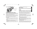
Anti-Lock Control (DW239, DW249)
Your D
EWALT drill may come with an electronic feature called Anti-
Lock Control. It is designed to help you control the drill during a stall
and keep it from pulling out of your hands. This may be encountered
when drilling in steel or using large bits in wood.
As a stall situation presents itself, the motor cycles on and off for a
set period of time. This takes up the reaction of the stall and allows
you to keep the drill under control. The speed control senses your
release of the trigger and resets the motor to run again.
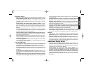
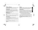
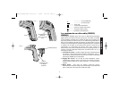
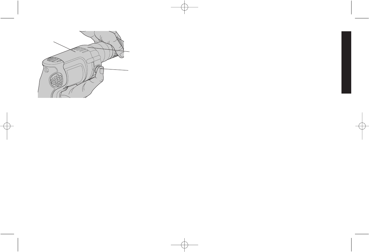
Figure 4 shows the instruction label mounted behind it. There are
three alert signals.
1.) Check Level: One flash each time the trigger is depressed.
Everything is functioning satisfactorily. If there is no flash, the tool
should be returned to a D
EWALT authorized service center for
repair.
2.) Engaged Level: Should a stall condition still exist, the electronics
will shut down the tool and the light will be steady on. When the
unit is running in normal mode, there will be no light.
3.) Alert Mode: A series of continual flashes as the trigger is pulled
indicates that the electronics are no longer functioning. The tool
may still be able to function without the benefit of AntiLock Control
but should be serviced as soon as possible.
Motor Brushes
DEWALT uses an advanced brush system which automatically stops
the drill when the brushes wear out. This prevents serious damage to
the motor.
Switch
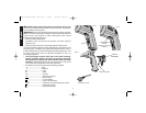
To start drill, depress trigger switch; to stop the drill, release trigger.
To lock trigger in the on position for continuous operation, depress
trigger and push up locking button “A” shown in figure 1, then gently
release the trigger. To release the locking mechanism, depress the
trigger fully, then release it. Before using the tool each time, be sure
that the locking button release mechanism is working freely.
Do not lock the switch on when drilling by hand so that you can
instantly release the trigger switch if the bit binds in the hole.
The locking button is for use only when the drill is mounted in a drill
press stand or otherwise held stationary.
Be sure to release the locking button before disconnecting the plug
from the power supply. Failure to do so will cause the tool to start
immediately the next time it is plugged in. Damage or injury could
result.
THE VARIABLE SPEED TRIGGER SWITCH
This switch permits speed control: the farther the trigger is de-
pressed, the higher the speed of the drill.
NOTE: Use lower speeds for starting holes without a center punch,
drilling in metal or plastics, driving screws or drilling ceramics. Higher
speeds are better for drilling wood and composition boards, and for
using abrasive and polishing accessories.
THE REVERSING LEVER
The reversing lever changes the direction of rotation of the drill and
is used when backing out screws and jammed drill bits. To operate
the tool in reverse, release the trigger switch and push the lever to
the left (when viewed from the chuck end) as shown in Figure 2. To
3
English
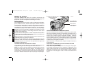
FIG. 4
SPINDLE LOCK
BUTTON
ANTI-LOCK CONTROL
INSTRUCTION LABEL
INDICATOR LIGHT
385932-02/NStar220 Drills.rev 7/2/02 3:49 PM Page 3