


9
Motor
Be sure your power supply agrees with nameplate marking. 120 Volts AC only means
your tool will operate on standard 60 Hz household power. Do not operate AC tools on
DC. A rating of 120 volts AC/DC means that your tool will operate on standard 60 Hz AC
or DC power. This information is printed on the nameplate. Lower voltage will cause loss
of power and can result in over-heating. All Black & Decker tools are factory-tested; if this
tool does not operate, check the power supply.
ASSEMBLY
WARNING: To prevent personal injury, always disconnect plug from power
source before assembly, making adjustments or changing bits. Failure to do so
could result in accidental starting and possible injury.
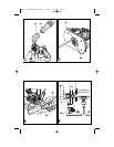
INSTALLING AND REMOVING A ROUTER BIT (FIG. A)
WARNING: Turn the router off and disconnect it from the power supply.
Installing
• Remove the chip shield (9).
• Keep the spindle lock button (5) depressed and rotate the spindle until the spindle lock
fully engages.
• Place the router upside down on a smooth, flat surface.
• Loosen the collet nut (16) using the spanner wrench provided.
• Insert the shank of the router bit (17) into the collet (6)(two collets are provided, 1/4” or
1/2”). Make sure that the shank protrudes at least 1/8” (3mm) from the collet as shown.
• Keep the spindle lock button (5) depressed and tighten the collet nut (16) using the
spanner provided.
Removing
CAUTION: Burn Hazard. Router bits get hot during use. Allow sufficient time for
bit to cool before replacing.
• Keep the spindle lock button (5) depressed.
• Loosen the collet nut (16) using the spanner wrench provided.
ATTACHING THE EDGE GUIDE (FIG. B)
WARNING: Turn the router off and disconnect it from the power supply.
The edge guide helps to guide the tool parallel to an edge.
• Fit the bars (18) to the edge guide (11) using the two screws (19) provided.
• Insert the bars (18) into the router base as shown.
• Set the edge guide to the required distance.
• Tighten the fixing screws (20).
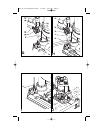
ATTACHING THE DUST EXTRACTION ADAPTOR (FIG. C)
The dust extraction adaptor allows you to connect a vacuum cleaner to the tool.
• Place the dust extraction adaptor (10) onto the dust extraction outlet as shown.
• Connect the hose (23) of the vacuum cleaner to the adaptor.
ATTACHING THE TEMPLATE GUIDE (FIG. C & D)
• Attach the template guide (12) to the base of the router, with the flange to the bottom side.
• Insert the two long screws (24) from the bottom side through the template guide and the
holes in the base.
• Place the dust extraction adaptor on top of the base as shown in fig. C.
• Place a nut onto each of the screws and securely tighten the nuts.
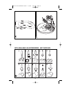
ATTACHING THE CENTERING PIN (FIG. E)
• Attach the edge guide to the router as shown in fig. B, but upside down.
• Attach the centering pin (14) to the workpiece side of the edge guide with the screw (25)
provided.
OPERATION
WARNING: To prevent personal injury, always disconnect plug from power
source before assembly, making adjustments or changing bits. Failure to do so
could result in accidental starting and possible injury.
WARNING: To reduce the risk of injury, do not overload the tool. Let it work at its
own pace.
492777-00 FS1200RP Router 2/6/06 1:02 PM Page 9