


10
ENGLISH
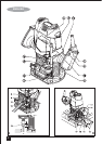
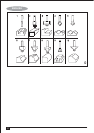
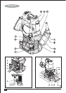
Fitting the dust extraction adaptor (fig. C)
The dust extraction adaptor allows you to connect a vacuum
cleaner to the tool.
• Connect the hose (18) of the vacuum cleaner to the
adaptor (11).
Fitting the template guide (fig. D)
• Fit the template guide (19) to the base of the router, with
the flange to the bottom (workpiece) side.
• Insert the two long screws (20) from the bottom side
through the template guide and the holes in the base.
• Place a nut onto each of the screws and securely tighten
the nuts.
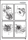
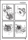
Fitting the distance piece (fig. E)
• Fit the distance piece (21) to the base of the router using
the screws provided.
Fitting the centring pin (fig. F)
• Fit the edge guide to the router as shown in fig. B, but
upside down.
• Fit the centring pin (22) to the workpiece side of the
edge guide with the screw (23) provided.
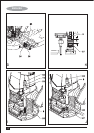
Fitting the copy follower (fig. G)
• Fit the edge guide to the router as shown in fig. B.
• Fit the ‘L' bar (24) to the upper side of the edge guide
using the two screws and nuts provided.
• Adjust the rotating attachment (25) on the ‘L' bar with the
wing knob (26).
Use
Warning! Let the tool work at its own pace. Do not overload.
• Carefully guide the cable in order to avoid accidentally
cutting it.
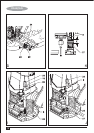
Adjusting the depth of cut (fig. H, I & J)
The depth of cut is the distance X between the depth stop bar
(9) and the depth stop (27). The depth of cut can be set in
two different ways as described below.
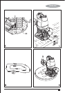
Adjusting the depth of cut using the scale (fig. I)
• Fit the router bit as described above.
• Loosen the locking screw (28).
• Pull the plunge lock lever (4) up.
• Plunge the router down until the router bit touches the
workpiece.
• Push the plunge lock lever (4) down.
• Move the pointer (29) in the zero position on the scale
(10).
• Add the desired depth of cut to the starting position.
• Move the depth stop bar (9) to the calculated position on
the scale.
• Tighten the locking screw (28).
• Fine adjust using the adjusting knob (30).
• Pull the plunge lock lever (4) up and let the router return
to its original position.
• After switching the router on, plunge it down and make
the desired cut.
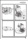
Adjusting the depth of cut using a piece of
wood (fig. J)
• Fit the router bit and plunge the router down as described
above.
• Pull the depth stop bar (9) up.
• Place a piece of wood with a thickness equal to the
desired depth of cut between the depth stop (27) and the
depth stop bar (9).
• Tighten the locking screw (28).
• Fine adjust using the adjusting knob (30).