


9
ENGLISH
• Children should be supervised to ensure that they do not
play with the appliance.
Residual risks.
Additional residual risks may arise when using the tool which
may not be included in the enclosed safety warnings. These
risks can arise from misuse, prolonged use etc.
Even with the application of the relevant safety regulations
and the implementation of safety devices, certain residual
risks can not be avoided. These include:
• Injuries caused by touching any rotating/moving
parts.
• Injuries caused when changing any parts, blades or
accessories.
• Injuries caused by prolonged use of a tool. When
using any tool for prolonged periods ensure you
take regular breaks.
• Impairment of hearing.
• Health hazards caused by breathing dust developed
when using your tool (example:- working with wood,
especially oak, beech and MDF.)
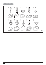
Labels on tool
The following pictograms are shown on the tool:
Warning! To reduce the risk of injury, the user must
read the instruction manual.
Electrical safety
This tool is double insulated; therefore no earth wire
is required. Always check that the power supply
corresponds to the voltage on the rating plate.
• If the supply cord is damaged, it must be replaced by the
manufacturer or an authorised Black & Decker Service
Centre in order to avoid a hazard.
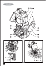
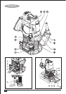
Features
1. On/off switch
2. Lock-off button
3. Variable speed control knob
4. Plunge lock lever
5. Spindle lock button
6. Collet
7. Revolver depth stop
8. Chip deflector
9. Depth stop bar
10. Depth of cut scale
11. Dust extraction adaptor
Assembly
Warning! Before assembly, make sure that the tool is
switched off and unplugged.
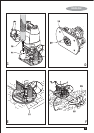
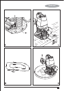
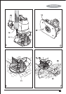
Fitting a router bit (fig. A)
• Remove the chip deflector (8).
• Keep the spindle lock button (5) depressed and rotate the
spindle until the spindle lock fully engages.
• Loosen the collet nut (12) using the spanner provided.
• Insert the shank of the router bit (13) into the collet (6).
Make sure that the shank protrudes at least 3 mm from
the collet as shown.
• Keep the spindle lock button (5) depressed and tighten
the collet nut (12) using the spanner provided.
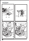
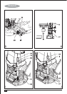
Fitting the edge guide (fig. B)
The edge guide helps to guide the tool parallel to an edge.
• Fit the bars (14) to the edge guide (15) using the two
screws (16) provided.
• Insert the bars (14) into the router base as shown.
• Set the edge guide to the required distance.
• Tighten the fixing screws (17).