11
screw firmly with wrench provided. (Turn counterclockwise,
left-hand threads)
5. Return the guard bracket to its original position and firmly tighten
the guard bracket screw to hold bracket in place.
WARNING:
• The guard bracket must be returned to its original position and
the screw tightened before activating the saw.
• Failure to do so may allow the guard to contact the spinning
saw blade resulting in damage to the saw and severe personal
injury.
Assembling and Adjusting Your Saw
PERFORM ALL ASSEMBLY WITH SAW UNPLUGGED.
ATTACH MITER CLAMP HANDLE
Remove the miter clamp handle (4) from the plastic parts bag and
carefully thread it into the bracket in the front of the saw.
Adjustments
PERFORM ALL ADJUSTMENTS WITH THE MITER SAW
UNPLUGGED
NOTE: Your miter saw is fully and accurately adjusted at the factory
at the time of manufacture. If readjustment due to shipping and
handling or any other reason is required, follow the steps below to
adjust your saw.
MITER SCALE ADJUSTMENT
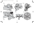
Place a square against the saw’s fence and blade, as shown in
Figure 6. (Do not touch the tips of the blade teeth with the square. To
do so will cause an inaccurate measurement.) Loosen the miter
clamp handle (4) as shown in Figure 7 and swing the miter arm until
the miter latch (5) locks it at the 0 miter position. Do not tighten the
clamp handle. If the saw blade is not exactly perpendicular to the
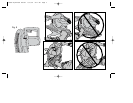
fence, loosen the two screws that hold the handle to the base (shown
in Figure 8) and move the arm of the saw left or right until the blade is
perpendicular to the fence, as measured with the square. Retighten
the two screws. Pay no attention to the reading of the miter pointer at
this point.
MITER POINTER ADJUSTMENT
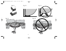
Loosen the miter clamp handle (4) and squeeze the miter latch (5) to
move the miter arm to the zero position. With the miter clamp handle
loose allow the miter latch to snap into place as you rotate the miter
arm past zero. Observe the pointer and miter scale (6) through the
miter latch opening. If the pointer does not indicate exactly zero,
loosen screw and re-align the pointer.
GUARD ACTUATION AND VISIBILITY
The blade guard on your saw has been designed to automatically
raise when the arm is brought down and to lower over the blade when
the arm is raised.
The guard can be raised by hand when installing or removing saw
blades or for inspection of the saw. NEVER RAISE THE BLADE
GUARD MANUALLY UNLESS THE SAW IS TURNED OFF.
NOTE: Certain special cuts will require that you manually raise the
guard. To do this, simply place your right thumb on the upper side of
the guard and roll the guard up just enough to clear the workpiece.
Never tie up or otherwise prevent the guard from operating normally.
The front section of the guard is louvered for visibility while cutting.
Although the louvers dramatically reduce flying debris, they are
openings in the guard and safety glasses should be worn at all times
when viewing through the louvers.
If you have any questions, call 1-800-54-HOW-TO.
630669-00,BT1000 manual 2/15/05 8:11 AM Page 11


