


English
14
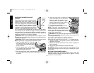
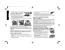
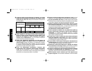
3. Securely tighten the two clamping
screws (W) supplied with the guard.
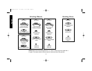
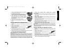
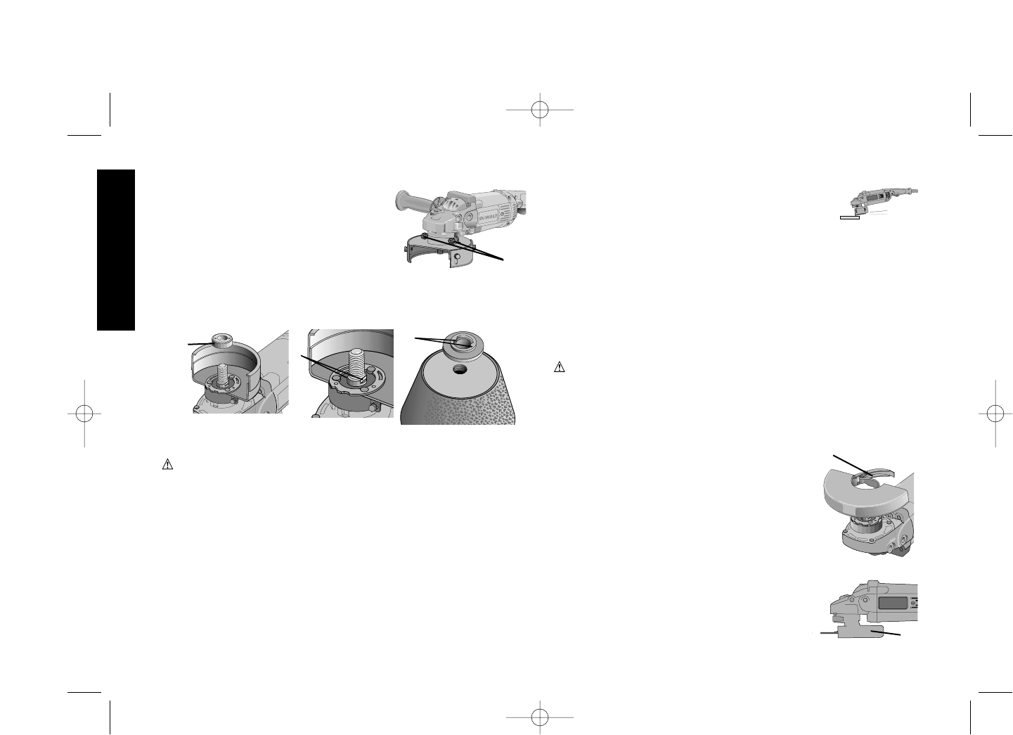
MOUNTING FLARING CUP WHEEL
1. Remove the soft mount (F).
2. Install the flaring cup wheel backing
flange, aligning the flats on spindle (O)
with the flats on backing flange (P).
3. Thread the flaring cup wheel on spindle by hand, seating wheel
against backing flange.
4. Depress the spindle lock button and tighten the wheel by hand.
5. To remove the wheel, reverse the above procedure.
CAUTION: Failure to properly seat the wheel against backing
flange before turning the tool on may result in damage to the tool or
the wheel.
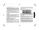
NOTE: Adjust the guard skirt so that only 1/8" of the wheel is
exposed by loosening the bolts, allowing the guard to lengthen.
Tighten the guard skirt bolts securely before using the grinder.
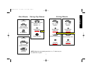
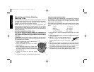
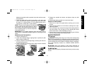
USING A FLARING CUP WHEEL
Flaring cup wheels are designed for heavy material removal.
1. Allow the tool to reach full speed before touching tool to work
surface.
2. Apply minimum pressure to work surface, allowing the tool to
operate at high speed.
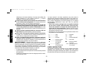
3. Maintain a 5˚ to 10
˚
angle between the tool and
the work surface.
4. Continuously move the tool in a forward and
back motion to avoid creating gouges in the work surface.
5. Remove the tool from work surface before turning tool off. Allow
the tool to stop rotating before setting it down.
Mounting and Using Cutting
(Type 1) Wheels
Cutting wheels include diamond wheels and abrasive discs.
Abrasive cutting wheels for metal and concrete use are available.
Diamond blades for concrete cutting can also be used.
WARNING: A closed, cutting wheel guard is not included with this
tool. Cutting wheels require proper flanges and guards. A 7" cutting
guard, D284931, is available as an accessory and includes proper,
matching flanges. Failure to use proper flange and guard can result
in injury resulting from wheel breakage and wheel contact.
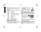
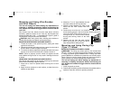
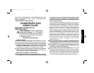
MOUNTING CLOSED (TYPE 1) GUARD
Turn off and unplug tool before making any
adjustments or removing or installing
accessories. Before reconnecting the tool,
depress and release the trigger switch to
ensure that the tool is off.
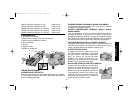
1. Open the guard latch (H), and align the lugs
with slots on the gear case cover. Position
the guard facing backward, as shown.
2. Push the guard down until the guard lug
engages and rotates freely in the groove on
the gear case hub.
3. Rotate guard (Q) into desired working posi-
tion. The guard body should be positioned
H
Q
5˚-10˚
F
O
P
W
399080-02 rev 11/15/02 10:13 AM Page 14