


-12-
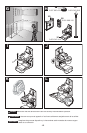
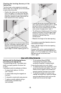
Working with the Positioning Device
(Accessory) (see figures I-Q)
The positioning device 17 provides easy
ability to properly position the laser line
or lines.
It attaches to job site surfaces as follows:
– To tripods with either a 1/4-20 or
5/8-11 mount
– To steel studs using the magnets on
the back
– To drywall or wood walls using screws
– To pipes or similar objects using a
commercially a
vailable strap
(not included)
– To the optional Bosch BP350
Telescoping Pole System 18 for
maximum versatility in setting height.
It can also be used a as a mini tripod.
• To attach the laser tool, screw the 1/4-20
mount into the tool and tighten. Turn the
knob and tool together as necessary to
properly position the laser line or lines.
• To adjust the height of the laser lines,
release the height lock, adjust the height
using the adjustment knob and turn the
height lock to secure the height.
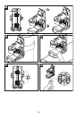
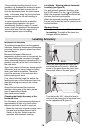
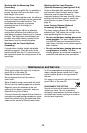
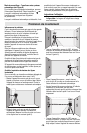
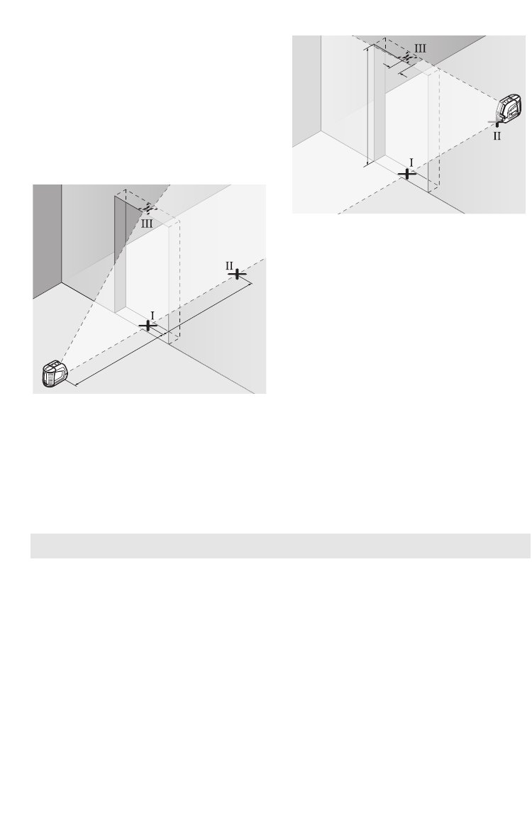
Checking the Leveling Accuracy of the
Vertical Line
For this check, a door opening is required
with at least 13 ft of space (on a firm surface)
to each side of the door.
– Position the tool on a firm, level surface
(not on a tripod) 13 ft away from the door
opening. Allow the tool to level in while in
cross-line operation mode, and direct the
laser beams at the door opening.
– Mark the center of the vertical laser line at
the floor of the door opening (point I), at a
dis
tance of 26 ft beyond the other side
of the door opening (point II) and at the
upper edge of the door opening (point III).
– Position the tool on the other side of the
door opening directly behind point II. Allow
the tool to level in and align the vertical
laser line in such a manner that its center
runs exactly through points I and II.
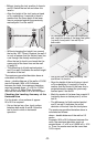
– The difference d between point III and the
center of the laser line at the upper edge
of the door opening results in the actual
deviation of the tool from the
vertical plane.
– Measure the height of the door opening.
The maximum permitted deviation dmax is
calc
ulated as follows:
dmax = double height of the door opening
x 0.0036 in/ft
Example: With a door opening height of 2
meters, the maximum permitted deviation is
dmax = 2 x 7 ft x 0.0036 in/ft = 0.05 in. Thus,
the marks must not be more than
0.05 in. apart.
13 ft
13 f
t
7 ft
d
Use with Attachments