


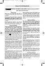
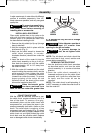
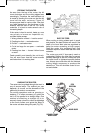

REMOVING MOTOR FROM BASE
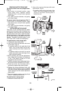
To remove motor from non-plunge bases:
(Fig. 6)
1. Hold router in horizontal position, open
b
ase clamp lever, depress coarse
adjustment lever, and pull motor upwards
until it stops.
2. Turn motor counter-clockwise, and gently
pull it free of base.
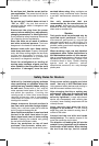
To remove motor from plunge base: (Fig. 7)
1. Hold router in horizontal position, open
base clamp lever, and pull motor upwards
until it stops.
2. Turn motor counter-clockwise, and gently
pull it free of base.
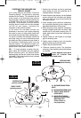
INSTALLING MOTOR IN BASE
The motor can be installed with the switch
positioned on the right or left of the base from
the operator's side (and the cord facing the
opposite side of the router). Install the motor
so that the switch is in the location you find to
be the most easily accessible from the
handles. The switch should be easier to turn
"OFF" than "ON" in case of an emergency.
To install motor in non-plunge base:
1. Release the base clamp lever.
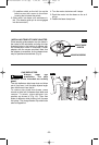
2. Line up the arrow on the base with arrow
on the motor. (Fig. 8)
•To position switch on the right side of the
base, line up the base’s arrow with
motor housing’s arrow that is below the
cord.
•To position switch on the left, line up the
base’s arrow with motor housing’s arrow
that is below the switch.
3.While pressing the coarse adjustment
lever, slide motor into base until resistance
in felt. (The base’s guide pin is now
engaged into slot on motor.)
4. Continue to press coarse adjustment lever,
and turn the motor clockwise until it stops.
5. Push the motor into the base until it
reaches the approximate desired depth.
6. Release the coarse adjustment lever and
slide the motor forward or back as needed
until the coarse adjustment system’s
“catch” springs into the coarse adjustment
detent notch.
7.
Set final height position as described
below in “Operating Instructions”.
To install motor in plunge base:
1. Release the base clamp lever.
2. Line up the arrow on the base with arrow
on the motor. (Fig. 8)
•To position switch on the right side of the
base, line up the base’s arrow with
a
rrow on the motor housing that is
below the cord.
-10-
ALIGNMENT
ARROWS
COARSE
ADJUSTMENT
NOTCHES
MOTOR
BASE
FIG. 8
BASE
CLAMP
LEVER
FIG. 6
COARSE
ADJUSTMENT
LEVER
BASE
CLAMP
LEVER
FIG. 7
BM 2610925542 07-06.qxp 7/24/06 12:06 PM Page 10